
Read a vacuum circuit breaker diagram in layers—the sealed interrupter first, then the mechanism that moves its contacts, then the outdoor pole or indoor armored package around them—so a construction cutaway is not mistaken for a wiring schematic or a ratings sheet.
The sections below label interrupter parts, follow the vacuum circuit breaker working principle to current zero, keep mechanism motion separate from the bottle, tell outdoor pole packages from indoor vacuum-trolley cabinets, and open one JOHNN outdoor vacuum breaker path when that is the next decision.
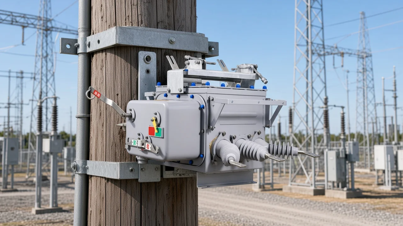
How to read a vacuum circuit breaker diagram in layers
Start with the sealed interrupter, then the mechanism that moves the contact, then the outdoor or indoor package around them.
Buyers often receive a supplier cutaway that mixes interrupter internals with cabinet outlines. Sorting those layers first keeps RFQ talk on the interrupting element instead of terminal blocks or nameplate cells.
| Layer | What to label first | Typical drawing cue |
|---|---|---|
| Interrupter | Envelope, fixed / moving contacts, bellows, shields | Sealed “bottle” cutaway |
| Mechanism | Spring, magnetic, or other actuator and linkage | Energy-store symbol, drive rods |
| Package | Outdoor sealed pole unit or indoor armored trolley | Pole tank outline or withdrawable truck |
A switchgear diagram for a vacuum breaker is still read the same way: interrupter physics first, then motion, then the package that carries both into the yard or the switchroom.
Vacuum interrupter parts to label on the diagram
Envelope, fixed and moving contacts, bellows, and arc/vapour shields are the core labels; contact shapes may appear for arc control.
On a vacuum circuit breaker diagram, start with the sealed vacuum interrupter that holds the fixed and moving contacts. The hermetic glass, ceramic, or metal housing is the interrupter envelope you see as the bottle outline.
Metal bellows keep vacuum integrity while the moving contact travels. Arc / vapour shield parts sit around the gap so metal vapour does not coat the envelope wall.
Many interrupter drawings also show RMF / AMF contact geometry—spiral, slotted, or axial-field electrodes that steer the vacuum arc and reduce local overheating. Plain butt contacts appear on lighter-duty switches; shaped contacts are the cue that arc control was designed into the interrupter.
How a vacuum circuit breaker works from closed contacts to current zero
Mechanism opens the moving contact; a metal-vapour arc forms; the arc collapses near current zero as vapour recondenses and the gap recovers.
In closed service the fixed / moving contacts carry load current through the vacuum interrupter. A trip command drives the operating mechanism so the moving contact separates by a short stroke.
Contact metal vapour then forms a brief plasma bridge across the gap. The interrupter extinguishes that metal-vapour arc / current zero event as vapour recondenses and dielectric strength returns in the vacuum gap.
Educational construction notes often place contact travel in the 5–10 mm class for many MV interrupters.
Operating mechanism versus the interrupter bottle
The mechanism is the motion source; the vacuum interrupter is the interrupting chamber—read them as separate diagram layers.
Spring energy-storage, motor-charged, or magnetic actuators appear on drawings as the drive that pulls the moving contact. That operating mechanism layer is not the vacuum bottle itself, even when the linkage is drawn next to the interrupter.
Outdoor product drawings that call out a spring mechanism are naming the motion engine. Keep that callout on the mechanism row of your three-layer scan before you open package or ratings talk.
From the field: A construction cutaway of the interrupter and linkage is not a CT/relay protection schematic—the protective relay + CT path decides when the trip coil fires, while the breaker itself is the electrically operated switch — community sizing threads make that split explicit when buyers expect overcurrent devices “inside” the vacuum breaker.
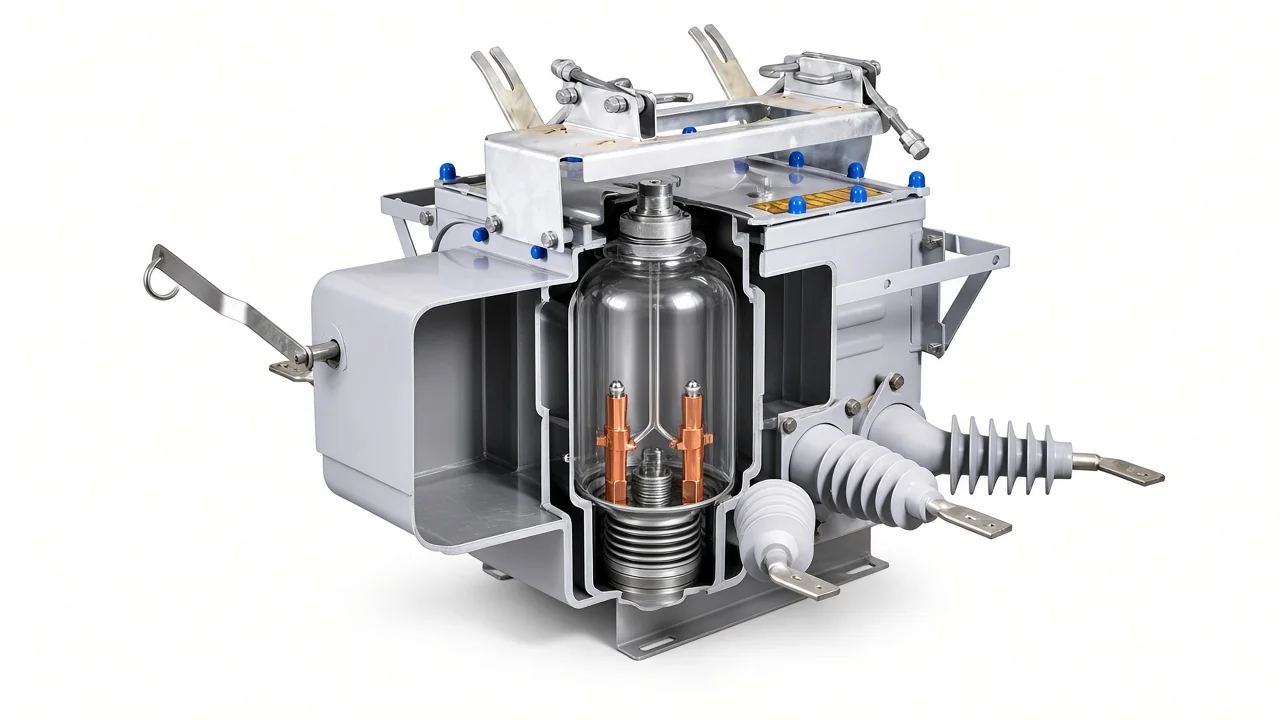
Outdoor pole packages versus indoor armored vacuum trolleys
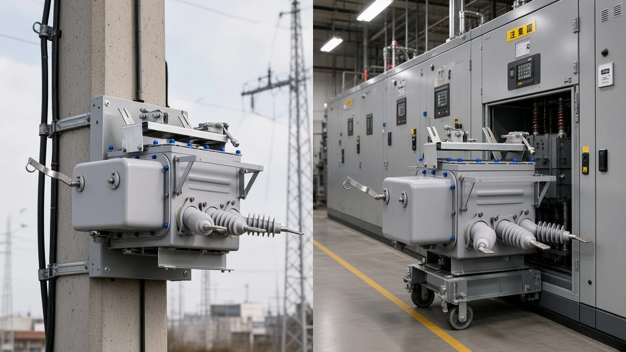
Outdoor sealed pole units and indoor metal-clad withdrawable trucks package the same interrupter idea differently.
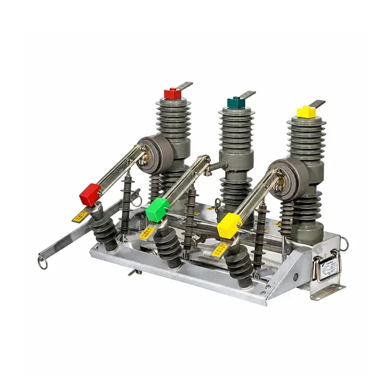
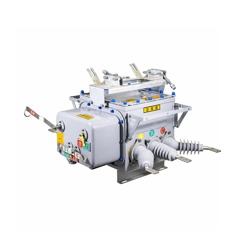
An outdoor vacuum circuit breaker package places the interrupters and mechanism inside a weather-facing sealed pole unit for distribution poles and outdoor structures. Indoor metal-clad panels often carry the VCB on a withdrawable truck—distinct from outdoor pole-mounted units.
KYN28A-12 fits when the drawing interest is a removable vacuum trolley inside a switchroom lineup. ZW32-12 remains an outdoor alternative when a permanent-magnetic mechanism fits better than a spring-operated outdoor package.
Project specs for MV AC breakers often reference the IEC 62271-100 family for systems above 1000 V. That framing covers indoor or outdoor AC breakers.
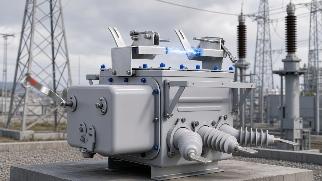
The outdoor sealed pole outline and the indoor trolley outline are the last layer to mark after interrupter parts and mechanism motion are clear on the same sheet.
Which JOHNN outdoor vacuum breaker fits after you can read the diagram?
ZW20-12 outdoor high-voltage vacuum circuit breaker—with a spring mechanism and sealed outdoor package. ZW32 and KYN28A remain alternatives when permanent-magnet outdoor duty or indoor armored trolley cabinets fit better.
Open the ZW20-12 outdoor high-voltage vacuum circuit breaker overview when the job needs an outdoor pole-mounted vacuum breaker with a spring mechanism and sealed outdoor cabinet after you can read the interrupter and mechanism layers.
ZW20-12 is rated 12 kV, three-phase 50 Hz, with rated current 630 A and short-circuit breaking current 20 kA on the ZW20 product overview. Peak closing / dynamic current is listed at 50 kA, with 4 s thermal current 20 kA and mechanical life 10000 times.
Important: ZW20 SF₆ language on the product overview is outdoor sealed-cabinet fill at a rated gauge pressure of 0.01 MPa—not the vacuum interrupter’s arc-quenching medium.
Service conditions on that overview include ambient −40 ℃ to +40 ℃ and altitude ≤1000 m for the published outdoor duty. Match those cells to the site envelope before treating the package as a drop-in for every climate.
| Hub sibling | Prefer ZW20-12 when… | Prefer the sibling when… |
|---|---|---|
| ZW32-12 | Spring-operated outdoor pole vacuum switching is the driver | Permanent-magnetic outdoor mechanism preference wins |
| KYN28A-12 | Outdoor sealed pole package matches the diagram job | Indoor armored withdrawable vacuum trolley packaging wins |
Browse the Switchgear Cabinets hub if indoor armored trolley packaging or a permanent-magnetic outdoor sibling is the real driver.
What this vacuum circuit breaker diagram page does not cover
Wiring/control schematics, deep specifications sheets, and pure definitional “what is VCB” essays stay fenced.
A vacuum circuit breaker wiring diagram with trip-coil terminals, CT secondary loops, and interlocking rails belongs in a later control-drawing package. Deep vacuum circuit breaker specifications / sizing tables and a full “what is vacuum circuit breaker in electrical” rewrite also stay outside this layered diagram reading.
Tip: Sealed vacuum bottles commonly lack oil-style vacuum-pressure alarms on the construction drawing—field crews replacing oil breakers often ask what replaces a low-pressure alarm, and peer replies note vacuum bottles are typically not monitored the way oil pressure was — Electrician Talk — Testing Vacuum Bottles.
FAQ
How does a vacuum circuit breaker work?
Closed contacts carry current through the vacuum interrupter; the mechanism opens the moving contact; a metal-vapour arc forms; the arc collapses near current zero as vapour recondenses; the vacuum gap recovers dielectric strength.
What parts should I look for on a vacuum circuit breaker diagram?
Label the interrupter envelope, fixed / moving contacts, metal bellows, and arc / vapour shield first, then the operating mechanism linkage, then the outdoor pole or indoor trolley package outline.
What is the difference between a VCB and an ACB?
A VCB interrupts inside a sealed vacuum interrupter and is typically packaged for medium-voltage duties; an ACB interrupts in air and is the common low-voltage assembly breaker form. Deep definitional essays on either device stay outside this diagram page.
What is a VCB used for?
Medium-voltage distribution, substation, and industrial plant switching of load, overload, and short-circuit current—either as an outdoor pole package or as an indoor armored vacuum trolley inside metal-clad switchgear.
Why use vacuum instead of oil or SF₆ as the interrupting medium?
Vacuum interrupters are sealed, recover dielectric strength quickly after current zero, and avoid oil as the arc medium. Outdoor cabinets may still use SF₆ as insulation fill around the package; that fill is not the interrupter arc medium.
Is a vacuum circuit breaker diagram the same as a wiring diagram?
No. A construction or working diagram labels interrupter and mechanism parts; a wiring or control schematic shows CT, protective relay, and trip-coil circuits that command the breaker.
What is the most serious problem people worry about with vacuum interrupters?
Loss of vacuum in a sealed-for-life bottle is the failure mode education sources and field threads emphasize; sealed bottles are not field-repaired like an oil tank, and many drawings omit a vacuum-pressure gauge.
Where does JOHNN ZW20-12 fit after you can read the diagram?
ZW20-12 is the outdoor spring-operated vacuum breaker with a sealed outdoor cabinet once you can read the interrupter and mechanism layers; choose ZW32-12 when permanent-magnetic outdoor duty fits better, or KYN28A-12 when the job is an indoor armored vacuum trolley.
References
- Wikipedia: Vacuum interrupter
- Switchgear Content: bellows role in vacuum interrupters
- Switchgear Content: vacuum circuit breaker contact shapes
- IEC webstore: AC circuit-breaker catalogue abstract
- Circuit Globe: vacuum circuit breaker
- ElectricalWorkbook: vacuum circuit breaker
- Electrician Talk — Testing Vacuum Bottles