Product Overview
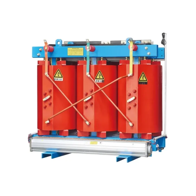
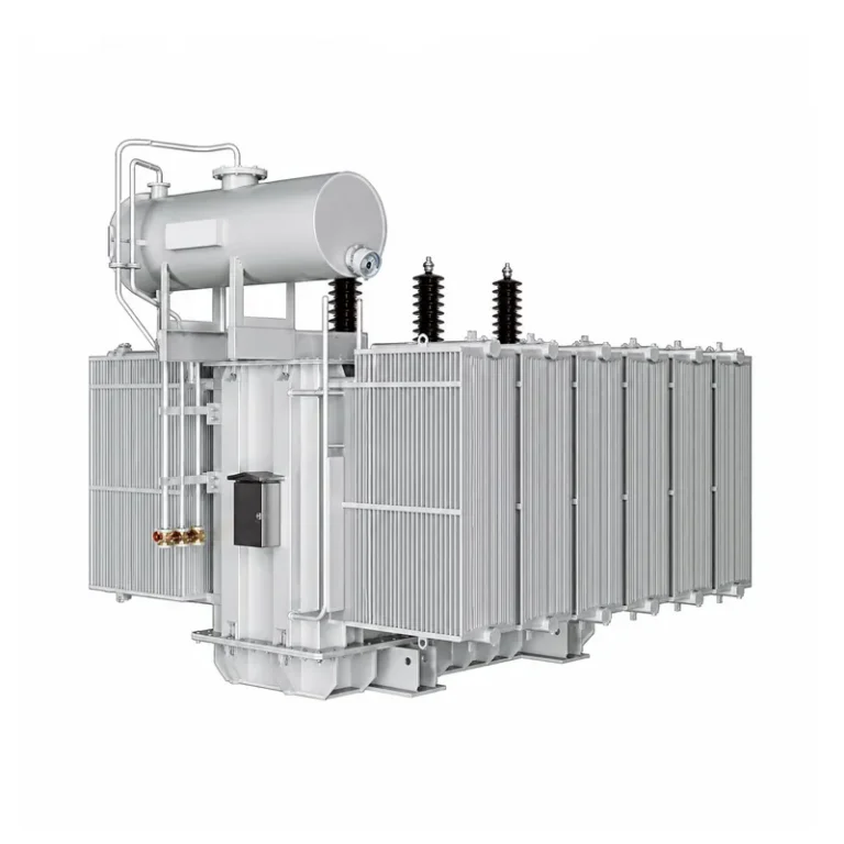
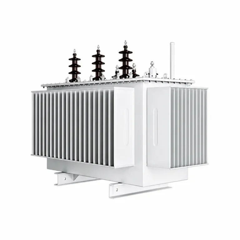
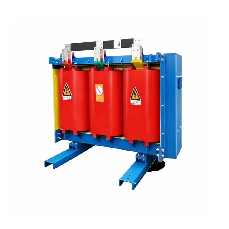
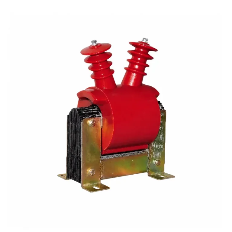
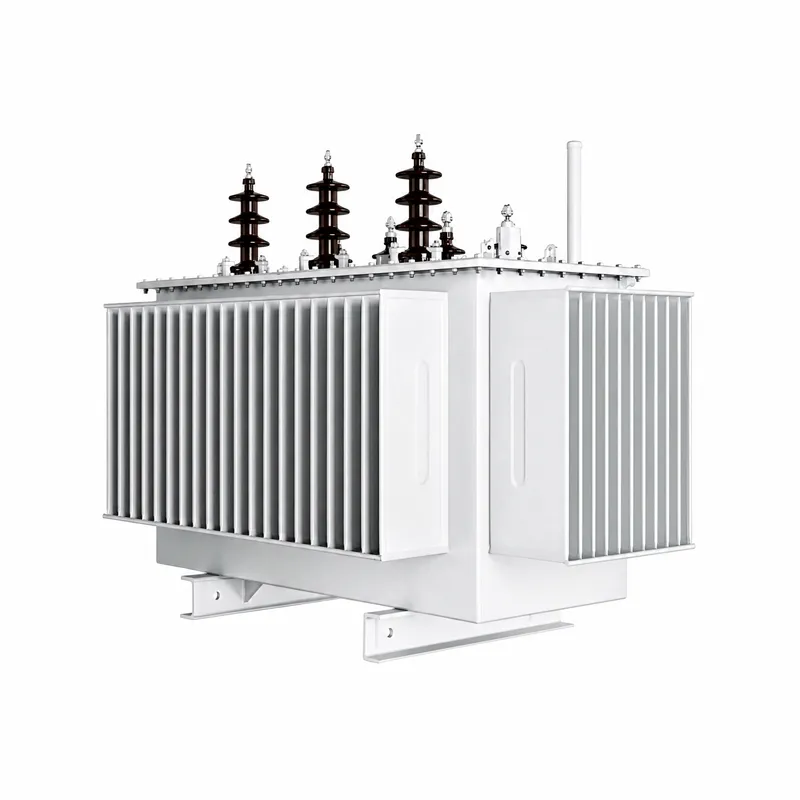
This amorphous alloy oil-immersed transformer uses amorphous alloy as core material, with insulating oil for cooling and insulation. It features extremely low core loss and remarkable energy saving. The fully sealed structure prevents oil leakage with maintenance-free performance. Low temperature rise slows insulation aging, suitable for outdoor power distribution, industrial & commercial sites and new energy projects. It is eco-friendly with lower overall power consumption during service life.
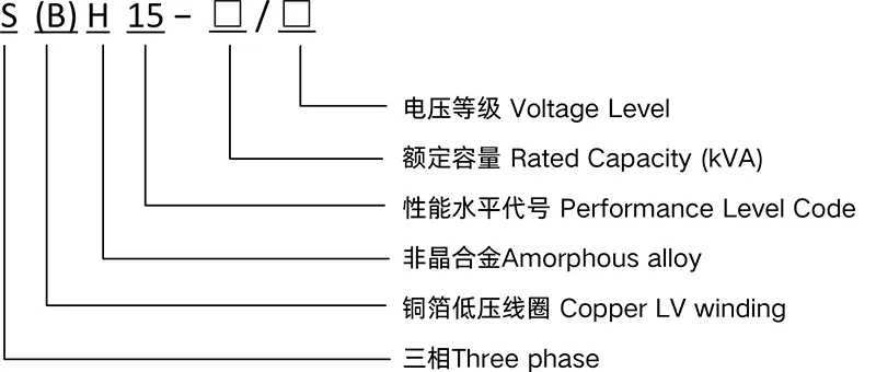
Model and Meaning
Transformer Normal Service Conditions
Altitude: not exceeding 1000m
Ambient temperature: Maximum air temperature: +40℃ Maximum daily average air temperature: +30℃
Maximum annual average air temperature: +20℃
Minimum outdoor air temperature: −25℃
Power voltage waveform approximates sine wave; three-phase power voltage is approximately symmetrical Installation environment: no obvious contamination
Seismic ground acceleration ag: horizontal value below 3m/s², vertical value below 1.5m/s²
Indoor usage
Note: If special service conditions outside the above normal ranges are required, relevant conditions shall be stated when requesting quotation and placing orders
Technical Parameters
S(B)H15 Series 6kV/ 10kV Class Amorphous Alloy Oil-Immersed Transformers
| Rated capacity (kVA) | Voltage Combinationed Tap Range | Vector Group Symbol | Loss (W) | No-load current (%) | Impedance voltage (%) | Weight (kg) | Overall dimension L×W×H | Track gauge Longitudinal / Transverse | |||||
| HV(kV) | HV Tap Range % | LV(kV) | No-load Loss | Load Loss | Body(kg) | Oil(kg) | Total(kg) | ||||||
| 30 | 11 10.5 10 6.3 6 |
±5 ±2×2. |
0.4 | Dyn11 | 33 | 630 | 1.5 | 4.0 | 240 | 80 | 410 | 920×600×980 | 400×550 |
| 50 | 43 | 910 | 1.2 | 310 | 110 | 510 | 950×620×1040 | ||||||
| 63 | 50 | 1090 | 1.1 | 350 | 125 | 570 | 990×670×1040 | ||||||
| 80 | 60 | 1310 | 1 | 410 | 135 | 630 | 1030×720×1040 | 400×660 | |||||
| 100 | 75 | 1580 | 0.9 | 475 | 150 | 720 | 1060×770×1070 | ||||||
| 125 | 85 | 1890 | 0.8 | 550 | 170 | 830 | 1060×900×1070 | ||||||
| 160 | 100 | 2310 | 0.6 | 630 | 190 | 960 | 1060×930×1150 | ||||||
| 200 | 120 | 2730 | 0.6 | 670 | 210 | 1040 | 1100×930×1170 | 550×820 | |||||
| 250 | 140 | 3200 | 0.6 | 750 | 240 | 1160 | 1180×1010×1180 | ||||||
| 315 | 170 | 3830 | 0.5 | 810 | 264 | 1240 | 1200×1010×1180 | ||||||
| 400 | 200 | 4520 | 0.5 | 860 | 290 | 1330 | 1270×1160×1200 | ||||||
| 500 | 240 | 5410 | 0.5 | 950 | 320 | 1460 | 1450×1240×1330 | 820×1070 | |||||
| 630 | 320 | 6200 | 0.3 | 1120 | 380 | 1860 | 1450×1240×1330 | ||||||
| 800 | 380 | 7500 | 0.3 | 4.5 | 1340 | 410 | 2230 | 1520×1380×1460 | |||||
| 1000 | 450 | 10300 | 0.3 | 1620 | 540 | 2700 | 1720×1460×1510 | ||||||
| 1250 | 530 | 12000 | 0.2 | 1900 | 640 | 3180 | 1780×1500×1690 | ||||||
| 1600 | 630 | 14500 | 0.2 | 2560 | 680 | 4240 | 1880×1540×1970 | ||||||
| 2000 | 750 | 18300 | 0.2 | 5.0 | 2900 | 980 | 4920 | 2080×1580×1970 | |||||
| 2500 | 900 | 21200 | 0.2 | 3940 | 1160 | 6560 | 2350×1580×2020 | ||||||
Note: The overall dimensions provided in this manual are for type selection reference only. Final dimensions shall be subject to the product outline drawing.
| Rated capacity (kVA) | Voltage Combinationed Tap Range | Vector Group Symbol | Loss (W) | No-load current (%) | Impedance voltage (%) | Weight(kg) | Overall dimension L×W×H | Track gauge Longitudinal / Transverse | |||||
| HV(kV) | HV Tap Range % | LV(kV) | No-load Loss | Load Loss | Body (kg) | Oil (kg) | Total (kg) | ||||||
| 30 | 11 10.5 10 6.3 6 |
±5 ±2×2.5 |
0.4 | Dyn11 | 33 | 630 | 1.5 | 4.0 | 240 | 80 | 410 | 920×600×980 | 400×550 |
| 50 | 43 | 910 | 1.2 | 310 | 110 | 510 | 950×620×1040 | ||||||
| 63 | 50 | 1090 | 1.1 | 350 | 125 | 570 | 990×670×1040 | ||||||
| 80 | 60 | 1310 | 1.0 | 410 | 135 | 630 | 1030×720×1040 | 400×660 | |||||
| 100 | 75 | 1580 | 0.9 | 475 | 150 | 720 | 1060×770×1070 | ||||||
| 125 | 85 | 1890 | 0.8 | 550 | 170 | 830 | 1060×900×1070 | ||||||
| 160 | 100 | 2310 | 0.6 | 630 | 190 | 960 | 1060×930×1150 | ||||||
| 200 | 120 | 2730 | 0.6 | 670 | 210 | 1040 | 1100×930×1170 | 550×820 | |||||
| 250 | 140 | 3200 | 0.6 | 750 | 240 | 1160 | 1180×1010×1180 | ||||||
| 315 | 170 | 3830 | 0.5 | 810 | 264 | 1240 | 1200×1010×1180 | ||||||
| 400 | 200 | 4520 | 0.5 | 860 | 290 | 1330 | 1270×1160×1200 | ||||||
| 500 | 240 | 5410 | 0.5 | 950 | 320 | 1460 | 1450×1240×1330 | 820×1070 | |||||
| 630 | 320 | 6200 | 0.3 | 1120 | 380 | 1860 | 1450×1240×1330 | ||||||
| 800 | 380 | 7500 | 0.3 | 4.5 | 1340 | 410 | 2230 | 1520×1380×1460 | |||||
| 1000 | 450 | 10300 | 0.3 | 1620 | 540 | 2700 | 1720×1460×1510 | ||||||
| 1250 | 530 | 12000 | 0.2 | 1900 | 640 | 3180 | 1780×1500×1690 | ||||||
| 1600 | 630 | 14500 | 0.2 | 2560 | 680 | 4240 | 1880×1540×1970 | ||||||
| 2000 | 750 | 18300 | 0.2 | 5.0 | 2900 | 980 | 4920 | 2080×1580×1970 | |||||
| 2500 | 900 | 21200 | 0.2 | 3940 | 1160 | 6560 | 2350×1580×2020 | ||||||
Notes:
①For a three-phase three-limb core, Yyn0 connection group mayalso be adopted as required.
②For transformers with rated capacity up to 500kVA, the load loss values above the slash in the table apply to Dyn11 or Yzn11 connection groups; the load loss values below the slash apply to Yyn0 connection group.