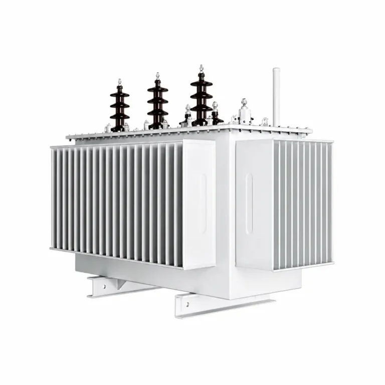
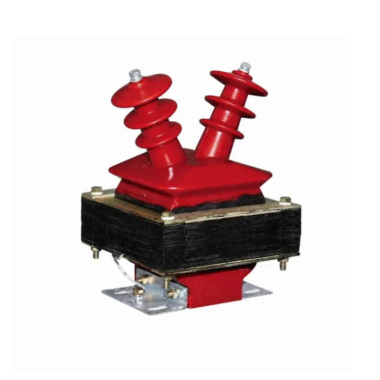
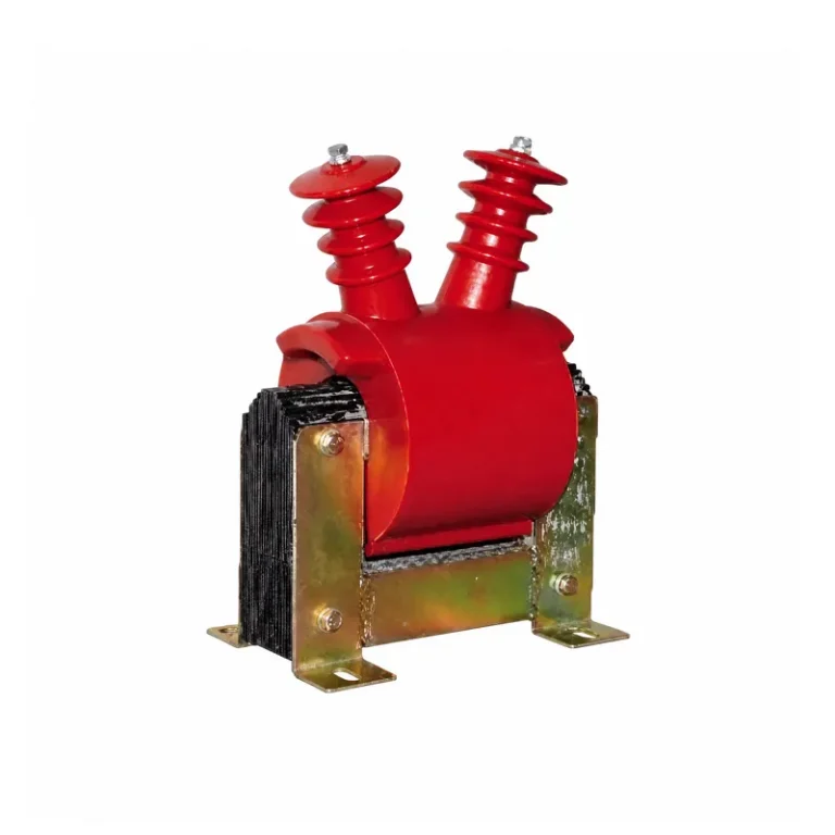
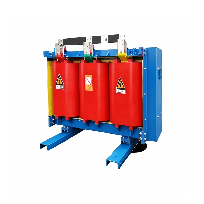
Product Overview
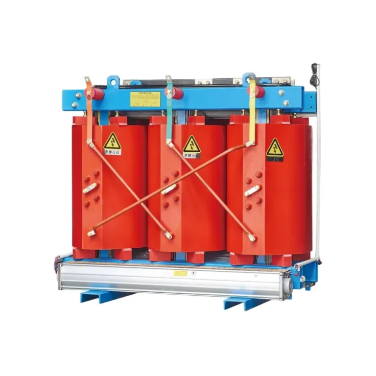
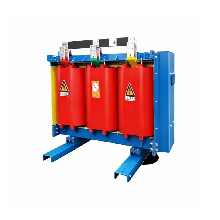
Dry-type amorphous alloy transformers adopt amorphous alloy for iron cores and use air for heat dissipation and insulation, with windings usually cast and solidified by epoxy resin. Featuring low no-load loss, excellent energy-saving performance, no risk of oil leakage and fire, as well as easy maintenance, they are widely applied to indoor power distribution scenarios such as buildings and industrial plants.
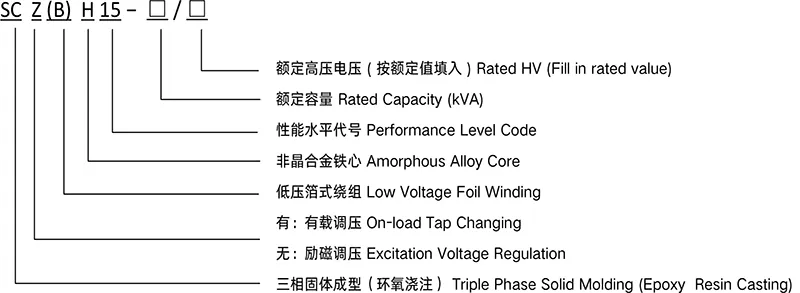
Model and Meaning
Service Conditions
- Maximum ambient temperature: +40℃
- Minimum ambient temperature: −5℃
- Average temperature of the hottest month: +30℃
- Average temperature of the hottest year: +20℃
- Altitude not exceeding 1000m
- Threephase supply voltages shall be approximately symmetrica
- Waveform of supply voltage approximates sine wave
- No obvious contaminants in installation environment
- Indoor application only
Technical Parameters
6~10kV Class SCBH15 Series Dry-type Off-Circuit Tap-Chnanging Amorphous Alloy Distribution Transformers
| Rated Capacity (kVA) | Voltage Combinationed Tap Range | Vector Group Symbol | No-load Loss (W) | Load Loss(W) | No-load Current % | Impedance Voltage % | ||||
| HV(kV) | HV Tap Range % | LV(kV) | 130℃(B)100℃ | 155℃(F)120℃ | 180℃(H)145℃ | |||||
| 30 | 6 6.3 6.6 10 10.5 11 |
±5 ±2×2.5 |
0.4 | Dyn11 | 70 | 670 | 710 | 760 | 1.6 | 4.0 |
| 50 | 90 | 940 | 1000 | 1070 | 1.4 | |||||
| 80 | 120 | 1290 | 1380 | 1480 | 1.3 | |||||
| 100 | 130 | 1480 | 1570 | 1690 | 1.2 | |||||
| 125 | 150 | 1740 | 1850 | 1980 | 1.1 | |||||
| 160 | 170 | 2000 | 2130 | 2280 | 1.1 | |||||
| 200 | 200 | 2370 | 2530 | 2710 | 1.0 | |||||
| 250 | 230 | 2590 | 2760 | 2960 | 1.0 | |||||
| 315 | 280 | 3270 | 3470 | 3730 | 0.9 | |||||
| 400 | 310 | 3750 | 3990 | 4280 | 0.8 | |||||
| 500 | 360 | 4590 | 4880 | 5230 | 0.8 | |||||
| 630 | 420 | 5530 | 5880 | 6290 | 0.7 | |||||
| 630 | 410 | 5610 | 5960 | 6400 | 0.7 | 6.0 | ||||
| 800 | 480 | 6550 | 6960 | 7450 | 0.7 | |||||
| 1000 | 550 | 7650 | 8130 | 8760 | 0.6 | |||||
| 1250 | 650 | 9100 | 9690 | 10370 | 0.6 | |||||
| 1600 | 760 | 11050 | 11730 | 12580 | 0.6 | |||||
| 2000 | 1000 | 13600 | 14450 | 15560 | 0.5 | |||||
| 2500 | 1200 | 16150 | 17170 | 18450 | 0.5 | |||||
| 1600 | 760 | 12280 | 12960 | 13900 | 0.6 | 8.0 | ||||
| 2000 | 1000 | 15020 | 15960 | 17110 | 0.5 | |||||
| 2500 | 1200 | 17760 | 18890 | 20290 | 0.5 | |||||
6~10kV Class SCBH15 Series Dry-type Off-Circuit Tap-Changing Amorphous Alloy Distribution Transformers
| Rated Capacity (kVA) | Voltage Combinationed Tap Range | Vector Group Symbol | No-load Loss (W) | Load Loss(W) | No-load Current % | Impedance Voltage % | ||||
| HV(kV) | HV Tap Range % | LV(kV) | 130℃(B)100℃ | 155℃(F)120℃ | 180℃(H)145℃ | |||||
| 30 | 6 6.3 6.6 10 10.5 11 |
±5 ±2×2.5 |
0.4 | Dyn11 | 70 | 670 | 710 | 760 | 1.6 | 4.0 |
| 50 | 90 | 940 | 1000 | 1070 | 1.4 | |||||
| 80 | 120 | 1290 | 1380 | 1480 | 1.3 | |||||
| 100 | 130 | 1480 | 1570 | 1690 | 1.2 | |||||
| 125 | 150 | 1740 | 1850 | 1980 | 1.1 | |||||
| 160 | 170 | 2000 | Q0 | 2280 | 1.1 | |||||
| 200 | 200 | 2370 | 2530 | 2710 | 1.0 | |||||
| 250 | 230 | 2590 | 2760 | 2960 | 1.0 | |||||
| 315 | 280 | 3270 | 3470 | 3730 | 0.9 | |||||
| 400 | 310 | 3750 | 3990 | 4280 | 0.8 | |||||
| 500 | 360 | 4590 | 4880 | 5230 | 0.8 | |||||
| 630 | 420 | 5530 | 5880 | 6290 | 0.7 | |||||
| 630 | 410 | 5610 | 5960 | 6400 | 0.7 | 6.0 | ||||
| 800 | 480 | 6550 | 6960 | 7450 | 0.7 | |||||
| 1000 | 550 | 7650 | 8130 | 8760 | 0.6 | |||||
| 1250 | 650 | 9100 | 9690 | 10370 | 0.6 | |||||
| 1600 | 760 | 11050 | 11730 | 12580 | 0.6 | |||||
| 2000 | 1000 | 13600 | 14450 | 15560 | 0.5 | |||||
| 2500 | 1200 | 16150 | 17170 | 18450 | 0.5 | |||||
| 1600 | 760 | 12280 | 12960 | 13900 | 0.6 | 8.0 | ||||
| 2000 | 1000 | 15020 | 15960 | 17110 | 0.5 | |||||
| 2500 | 1200 | 17760 | 18890 | 20290 | 0.5 | |||||
Notes: ① The load losses listed in the table are values obtained at the reference temperatures specified in parameters for different insulation systems (in accordance with GB/T 1094.1-11).
② If other vector group symbols are adopted, specific requirements shall be determined through negotiation between the manufacturer and the user.