Product Overview
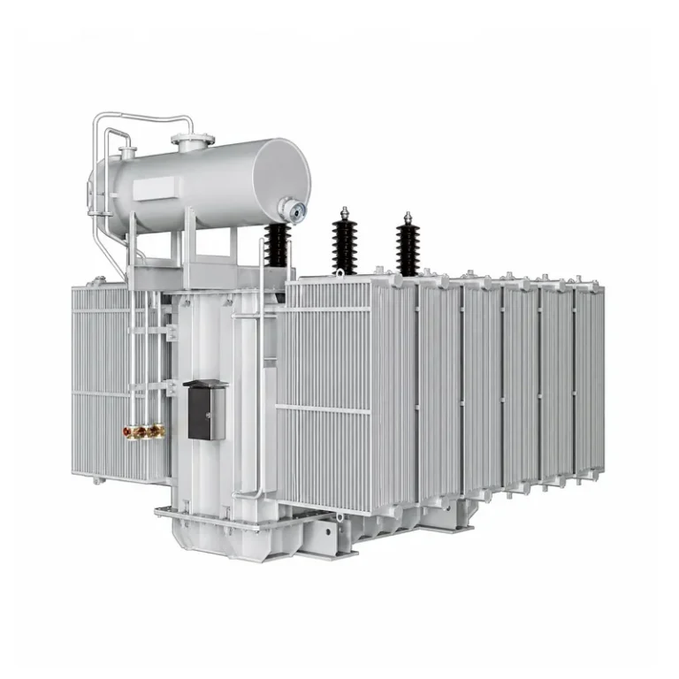
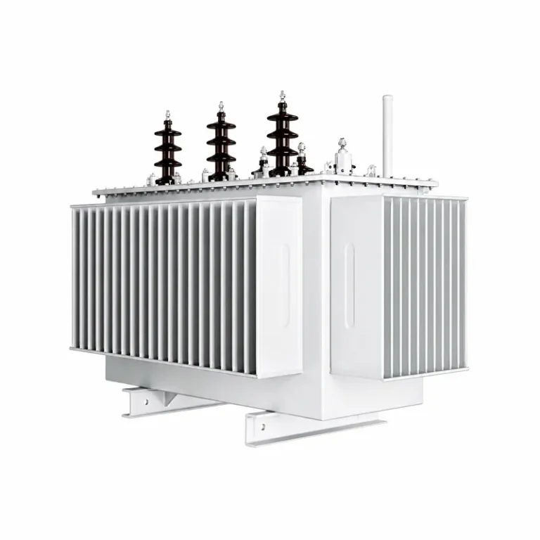
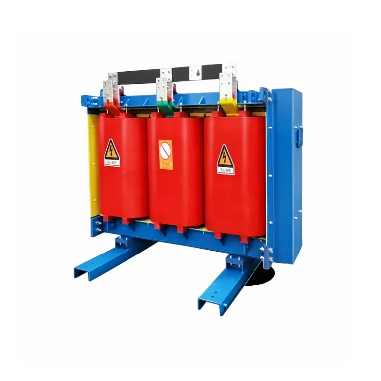
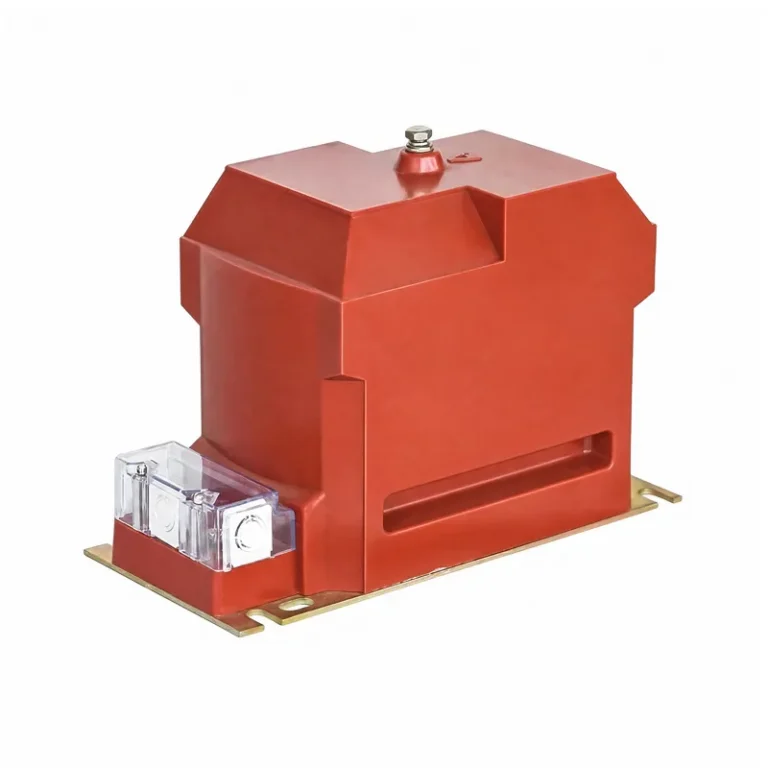
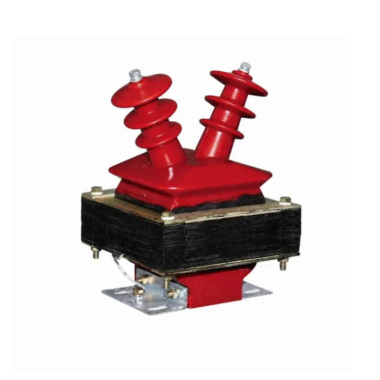
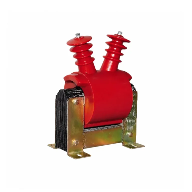
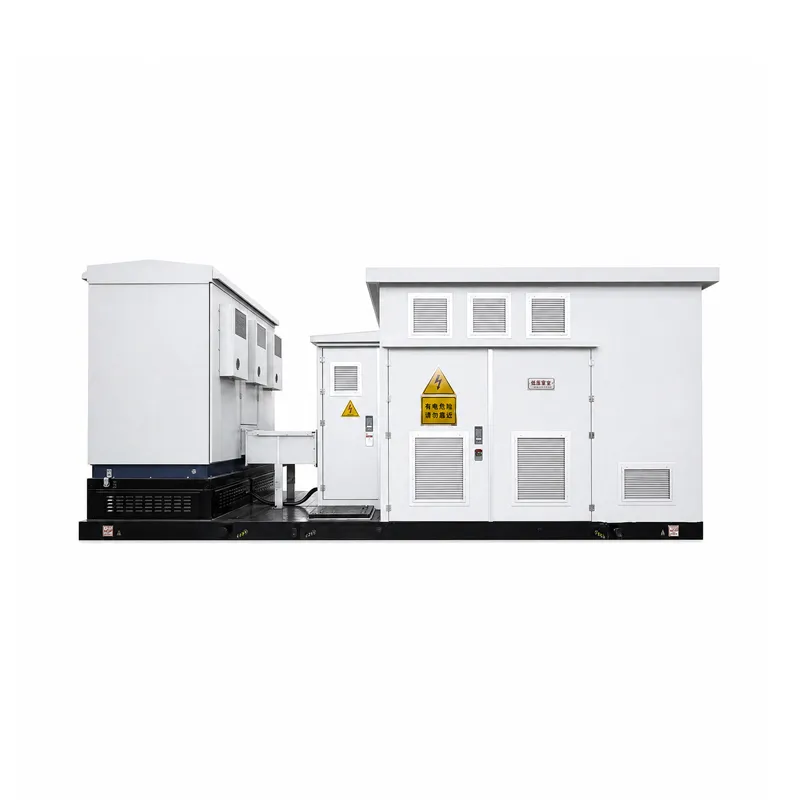
The photovoltaic inverter booster integrates inverter, transformer, power distribution and protection units, realizing integrated DC-AC conversion and voltage boosting for photovoltaic power. Featuring modular integrated design, it enables convenient installation and saves on-site space. Widely applied in centralized photovoltaic power stations to ensure stable grid connection of solar power.
Service Conditions
Operating Environmental Conditions
Installation Site: Outdoor fixed horizontal foundation, concrete or steel platform Altitude: ≤2000 m Minimum ambient temperature: -45 ℃ or -25 ℃
Maximum ambient temperature: +60 ℃
Relative humidity: ≤95% (daily average), occasional condensation
Storage Environmental Conditions
Storage Site: Outdoor area without special protection
Ground slope: ≤15 °
Minimum ambient temperature: -40 ℃
Maximum ambient temperature: +70 ℃
Relative humidity: ≤95% (daily average), occasional condensation
Functional and Performance Requirements
The low-voltage power supply for the integrated unit is drawn from the low-voltage side of the step-up transformer, using two transformers: one three-phase transformer for auxiliary power to the integrated unit and inverter, and one single-phase transformer for inverter control power. The auxiliary power supply includes a UPS (Uninterruptible Power Supply) to power critical equipment such as communication, fire protection, and monitoring systems. The UPS is an AC220V single-input, single-output tower type.
The low-voltage power supply circuit topology is shown in the diagram below. Specific capacity, number of circuits, and switch configuration will be adjusted according to project requirements.
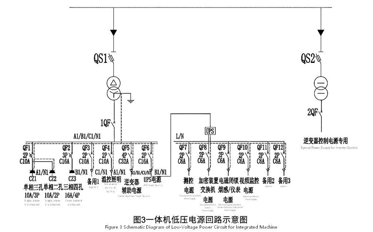
The photovoltaic inverter-boost integrated unit combines an outdoor photovoltaic inverter (provided by the buyer), a boost transformer, high-voltage switchgear, low-voltage auxiliary power supply, communication, and monitoring equipment into a single integrated device. It features an independent self-powering system, temperature and humidity control system, fire alarm system (smoke detectors), fire protection system (fire extinguishers), lighting system, and power supply and network access capabilities for video surveillance systems.
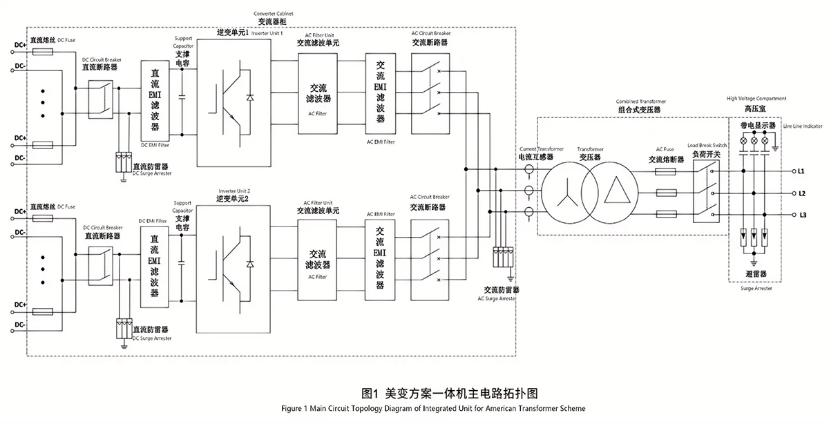
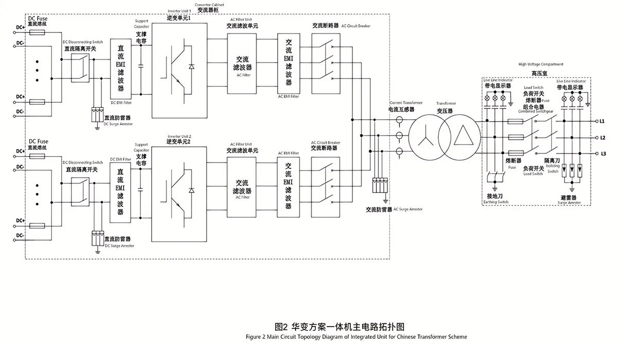
The entire unit is installed on a common base. The main circuit uses busbar connections, and components such as bushings that cannot withstand significant stress require flexible connections. The main circuit topology of the integrated unit is shown in the diagram below (the internal topology diagram of the inverter cabinet is for reference only).
Inverter Technical Parameters
| Item | Value/Content |
| Rated AC Output Power | 3125kVA |
| Maximum AC Output Power | 3437kVA |
| Rated AC Output Voltage | 600V |
| Allowable AC Output Voltage | 510V ~ 660V |
| Rated Grid Frequency | 50Hz |
| Allowable Grid Frequency | 45Hz ~ 55Hz |
| Number of AC Output Circuits / Phases | 1 circuit / 3-phase |
| Load Capacity | 3125kVA@50℃ (rated load) 3437kVA@45℃ (1.1 times overload) |
| Output Current Total Harmonic Distortion | ≤3% (under rated power) |
| Adjustable Power Factor Range | -0.8 (leading) ~ +0.8 (lagging) |
| DC Component | ≤0.5% (under rated current) |
| Protection Class | IP55 |
| Weight | 2270kg |
| Standby Power Consumption | <200W |
| Control Power Supply Requirement | AC220V/50Hz/Single-phase, 500VA |
| Auxiliary Power Supply Requirement | AC400V/50Hz/3P4W, 5000VA |
| Heat Dissipation & Cooling Method | Intelligent Forced Air Cooling |
| Maximum Operating Altitude | 5000m (derated operation above 3000m) |
| Operating Ambient Temperature | -35℃ ~ 60℃ |
| Operating Ambient Humidity | 0 ~ 95%, non-condensing |
| Communication Interface | 1 channel each for RS485 and RJ45 |
Technical Parameters of Low-Voltage Side AC Circuit Breakters
| Item | Overall Technical Requirements for Integrated Unit |
| Mounting Structure | Fixed Type |
| Number of Poles | 3 |
| Rated Current (A) @ 40℃ | 2000 |
| Rated Operational Voltage (V) | AC690 |
| Rated Frequency (Hz) | 50 |
| Rated Insulation Voltage (V) | 1000 |
| Rated Impulse Withstand Voltage (kV) | 12 |
| Total Breaking Time (ms) | <30 |
| Closing Time (ms) | <70 |
| Rated Ultimate Short-Circuit Breaking Capacity (r.m.s.) (kA) | 65 |
| Rated Operational Short-Circuit Breaking Capacity (r.m.s.) (kA) | 65 |
| Rated Short-Circuit Making Capacity (peak) (kA) | 143 |
| Rated Short-Time Withstand Current (r.m.s.) (kA) (1s) | 40/50 |
| Electrical Endurance (Operations) | 5000 |
| Electrical Topology | 2 MPPT channels with one unit each, parallel output |
Overall Technical Performance Requirements of IntegratedBooster Unit
| Item | Specification Requirements |
| Maximum DC Input Voltage | 1500V |
| Minimum Input Voltage / Start-up Voltage | 875V/915V |
| Full-load MPPT Voltage Range | 875V ~ 1300V |
| Number of MPPT Channels | 2 |
| Maximum DC Input Strings | 16 (18/20/22/24 optional) |
| Maximum DC Input Current | 3968A |
| Maximum DC Short-circuit Current | 5000A |
| AC Output Power | 3125kVA@50℃ (rated load) 3437kVA@45℃ (1.1 times overload) |
| Grid Voltage Level | 35kV |
| Maximum Grid Operating Voltage | 40.5kV |
| Rated Grid Frequency | 50Hz |
| Grid Frequency Range | 45Hz ~ 55Hz |
| Total Current Harmonic Distortion | ≤3% (at rated power) |
| DC Component | ≤0.5% (at rated current) |
| Power Factor | 0.99 (at rated power) |
| Adjustable Power Factor Range | 0.8 (leading) ~ 0.8 (lagging) |
| Feeder Phase Number / Output Terminal Phase Number | 3/3 |
| Protection Class | IP55 |
| Anti-corrosion Grade | Determined according to project requirements (C3, C4, C5) |
| Auxiliary Power Supply | 3-phase 4-wire, 15kVA+2kVA |
| UPS Unit | AC220V single input & single output |
| Transformer Cooling Method | Oil Natural Cooling |
| Inverter Cooling Method | Temperature-controlled Forced Air Cooling |
| HV & LV Cabinet Cooling Method | Forced Air Cooling |
| Operating Temperature Range | -35℃ ~ +60℃ (derated operation above 50℃) |
| Operating Humidity Range | 0~100% |
| Altitude | 2000m (customized for altitude above 2000m) |
| Communication | RS485 / Ethernet |
Live Line Indicator
| Item | Value |
| Voltage Class | 40.5kV |
| Core Capacitance | >40pF |
| Power Frequency Withstand Voltage | 100kV/5min (primary to secondary), 2kV/1min (secondary to earth) |
| Partial Discharge | <10pC |
| Standard Requirements | Comply with GB 25081-2010, DL/T 538-2006 |
| Others | With interlock and phase identification function |
| Independently configured for American Transformer scheme, 1 input circuit; integrated into fuse-load switch composite apparatus for Chinese Transformer scheme, configured on input side. | |
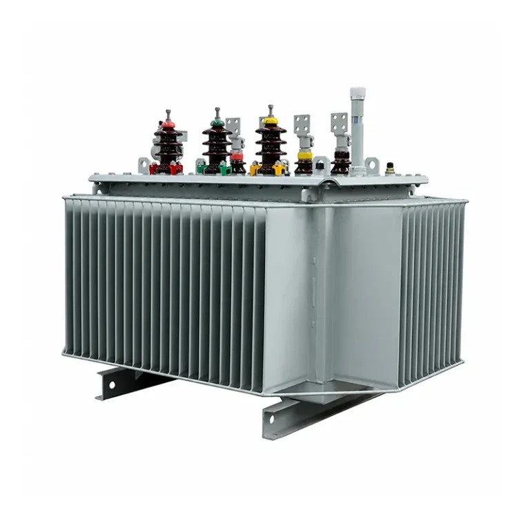
Transformer Technical Parameters
| Item | Specification Requirements |
| Rated Capacity (kVA) | 3150 |
| Overload Capacity | 1.1 times overload long-term operation at ambient temperature 45℃ |
| Rated Voltage (HV Side) (kV) | 35kV class (36.75kV, 37kV, 38.5kV, etc.) |
| Rated Voltage (LV Side) (kV) | 0.6 or 0.63 |
| HV Voltage Regulation Method | Off-circuit Manual Tap-changer |
| HV Tap Range | ±2×2.5%, comply with GB10230.1-2007 requirements |
| Vector Group | Dy11 or Yd11 |
| Number of Phases | 3-phase |
| Frequency (Hz) | 50 |
| Cooling Method | ONAN |
| Insulation Level | In accordance with GB311.1 |
| Sound Level | In accordance with JB/T10088 (70dB) |
| Temperature Rise | Top-oil temperature rise ≤60K |
| Short-circuit Impedance | 6%, 6.5%, 7%, etc. |
| Load Loss | 27.6kW / 21.9kW |
| No-load Loss | 2.8kW / 2.4kW |
| Total Loss | 30.4kW / 24.3kW |
| Transformer Oil | 25# or 45# |
| Silicon Steel Sheet | Baosteel, grade 30QG120 or above |
| HV Bushing | 40.5kV 100A resin bushing |
| LV Bushing | 1kV 4000A resin or porcelain bushing |
Note: Other Requirements for Transformer
1.Each phase AC busbar of the transformer shall be marked with corresponding phase sequence identification. The phase sequence on the low-voltage side shall be consistent with that of the inverter.
2.The tap terminals of the transformer shall be convenient for connection adjustment and provided with clear markings.
3.The transformer shall be reliably earthed, equipped with corresponding earthing terminals and identification marks.
4.Sealing parts of the oil tank shall be reliable and durable without oil leakage.
5.Welding and assembly of the tank shall be firm. Weld seams shall be smooth and uniform, free of burn-through, cracks, spatter, blowholes and other defects.
6.The tank shall be treated for rust prevention to ensure uniform paint film color and strong adhesion. No cracks, spots, bubbles or attachments are allowed.
7.Auxiliary protection and monitoring equipment shall comply with standards such as GB/T 1094.1 and GB/T 6451. The transformer shall be equipped with Buchholz relay, conservator, oil level gauge, pressure relief valve, top oil temperature detection, oil temperature indicator and other monitoring devices.
8.The transformer shall be provided with oil filling hole, oil drain valve, oil sampling port, etc., and anti-oil-theft measures shall be adopted.
Technical Parameters of High-Voltage Load Switch
| Item | Suitable for American Transformer | Suitable for Chinese Transformer |
| Rated Voltage | 40.5kV | 40.5kV |
| Frequency | 50Hz | 50Hz |
| Rated Current of Load Switch | 630A | 630A |
| Rated Short-Time Withstand Current | 31.5kA/4s | 31.5kA/4s |
| Rated Peak Withstand Current | 80kA | 80kA |
| 1-min Power Frequency Withstand Voltage | 95kV phase-to-earth & phase-to-phase; 118kV across isolating gap | 95kV phase-to-earth & phase-to-phase; 118kV across isolating gap |
| Lightning Impulse Withstand Voltage (peak) | 185kV phase-to-earth & phase-to-phase; 215kV across isolating gap | 185kV phase-to-earth & phase-to-phase; 215kV across isolating gap |
| Arc Extinguishing Medium | Transformer Oil | Vacuum |
| Auxiliary Contacts | 2NO + 2NC (independent wiring) | Min. 2NO + 2NC (independent wiring) |
| Operating Mechanism | Spring energy storage, manual operation | Motor operation |
| Standard Requirements | Comply with JB/T 10681-2006 | Comply with GB 16926-2009 |
| Others | Earthing switch & disconnector equipped with electromagnetic interlock | Equipped with input-side disconnector, input-side fuse mounting device and output-side earthing switch |
Technical Parameters of Fuse
| Item | Suitable for American Transformer | Suitable for Chinese Transformer |
| Model & Specification | XRNT-40.5kV/100A/S/H2-31.5kA | XRNT-40.5kV/100A/S/H2-31.5kA |
| Rated Voltage | 40.5kV | 40.5kV |
| Rated Current | 100A | 100A |
| Maximum Breaking Current | 31.5kA | 31.5kA |
| Mounting Method | Installed inside dedicated transformer tank; operable & maintainable from operating compartment | Installed in combination with fuse-load switch composite apparatus |
| Others | With auxiliary contact | With output signal indication |
| Standard Requirements | Comply with GB/T 15166.2-2008 | Comply with GB/T 15166.2-2008 |
Technical Parameters of High-Voltage Surge Arrester
| Item | Value |
| Rated Voltage | 51kV phase-to-earth |
| Continuous Operating Voltage | 40.8kV phase-to-earth |
| Residual Voltage under Switching Impulse Current | ≤114kV (peak) |
| Residual Voltage under Lightning Impulse Current | ≤134kV (peak) |
| 2ms Square Wave Discharge Capacity | ≥400A |
| Discharge Counter | 3 sets |
| Standard Requirements | Comply with GB 11032-2020 |
Interface Requirements
American Transformer Scheme
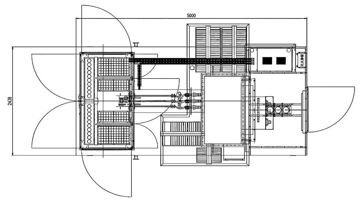
1.Base dimension: 2438cm × 5000cm, height within 2700mm
2.Reference weight: <15000kg (subject to final design confirmation)
3.Cables enter from the bottom of the high-voltage compartment. Space shall be reserved for incoming/outgoing routing and termination of three circuits of 3-core cables (including copper-aluminum transition connections).
4.The bottom of the inverter shall meet the requirements for DC cable entry and air outlet. Corresponding positions on the integrated unit base shall be kept vacant.
5.Three sets of independent copper connection busbars shall be adopted for high-voltage cable termination.
6.Cable entry holes are arranged at the B-phase interface to prevent cable twisting during installation, and cable fixing devices shall be installed at the cable penetration holes.
7.An oil collecting tray shall be fitted on the base. Its size shall extend no less than 30mm beyond the outer projection of the radiator, with a depth of no less than 40mm. Interfaces for drainage pipelines shall be reserved at appropriate positions inside the base.
8.Dimensional tolerances shall comply with the lowest grade specified in GB/T 1804-2000 General Tolerances − Tolerances for Linear and Angular Dimensions without Individual Tolerance Indications.
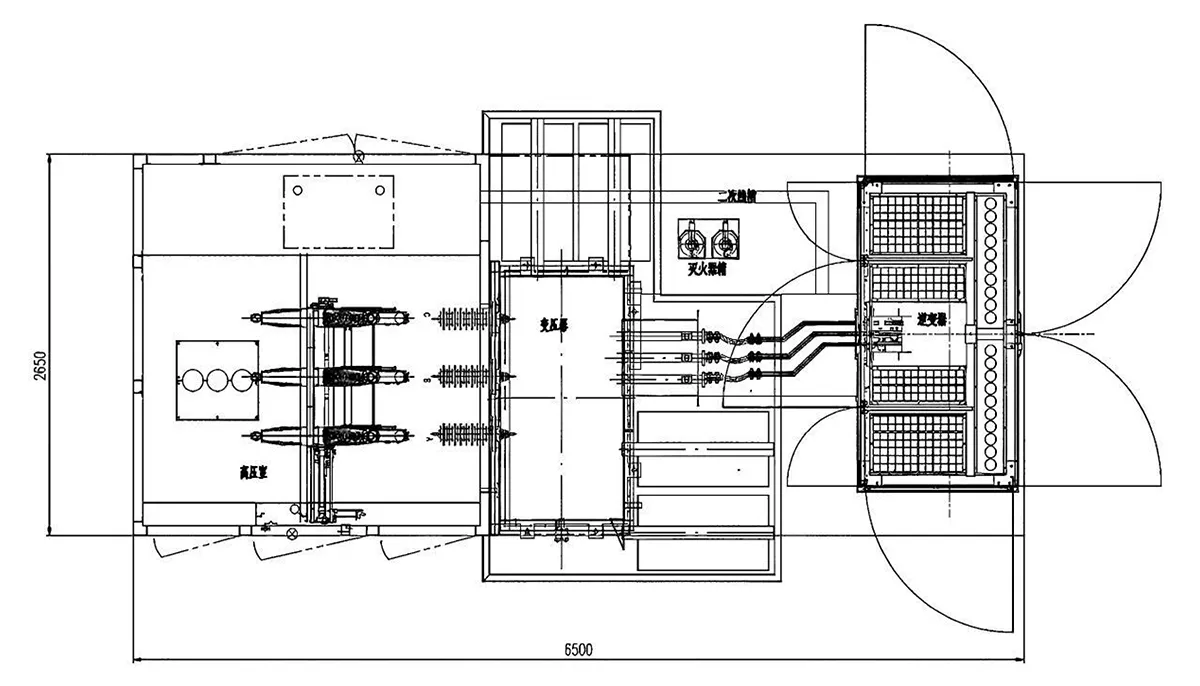
Refer to the figure below for the layout.
Chinese Transformer Scheme
1.Base dimension: 2650cm × 6500cm, height within 2700mm
2.Reference weight: <20000kg (subject to final design confirmation)
3.Cables enter from the bottom of the high-voltage compartment. Space shall be reserved for incoming/outgoing routing and termination of three circuits of 3-core cables (including copper-aluminum transition connections).
4.The bottom of the inverter shall meet the requirements for DC cable entry and air outlet. Corresponding positions on the integrated unit base shall be kept vacant.
5.Three sets of independent copper connection busbars shall be adopted for high-voltage cable termination.
6.Cable entry holes are arranged at the B-phase interface to prevent cable twisting during installation, and cable fixing devices shall be installed at the cable penetration holes.
7.An oil collecting tray shall be fitted on the base. Its size shall extend no less than 30mm beyond the outer projection of the radiator, with a depth of no less than 40mm. Interfaces for drainage pipelines shall be reserved at appropriate positions inside the base.
8.Dimensional tolerances shall comply with the lowest grade specified in GB/T 1804-2000 *General Tolerances − Tolerances for Linear and Angular Dimensions without Individual Tolerance Indications*.
Refer to the figure below for the layout.