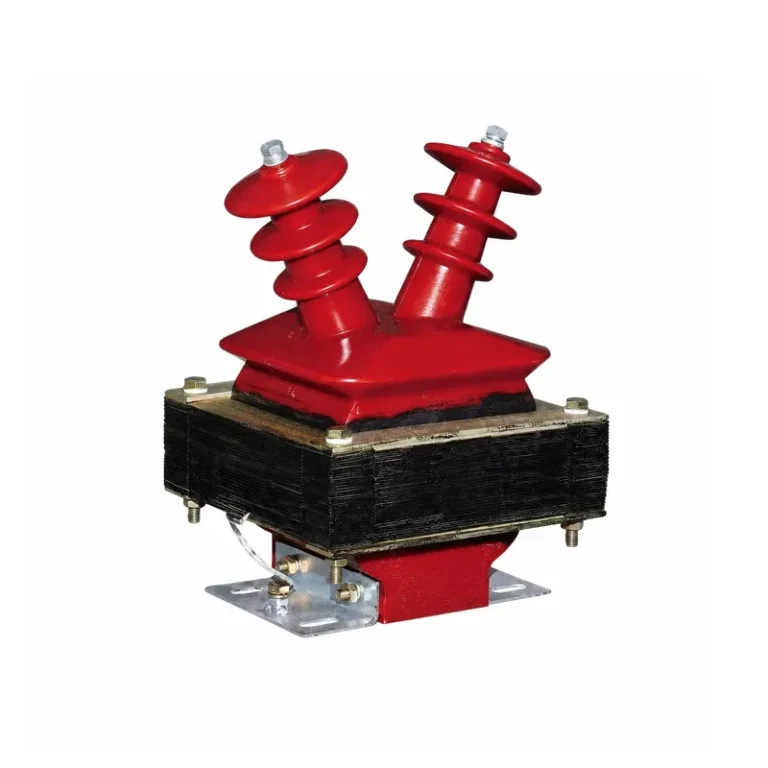
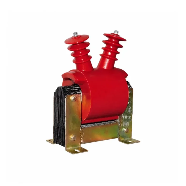
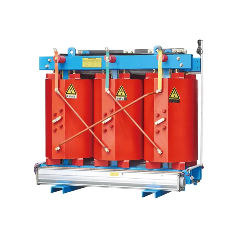
Product Overview
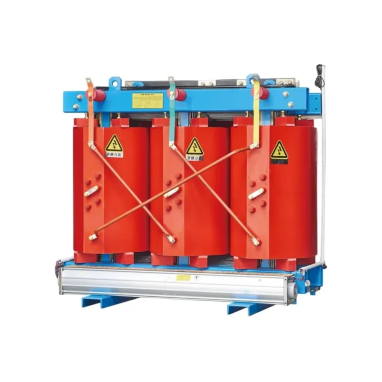
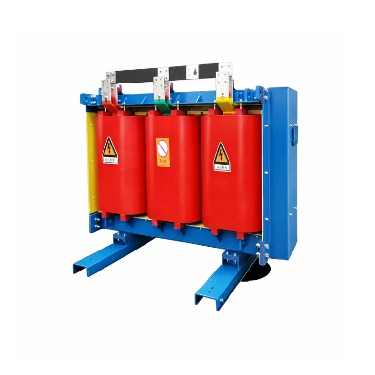
Resin-insulated dry-type transformers feature high safety, flame retardancy and zero pollution, and can be installed directly at load centers. They are maintenance-free and easy to install, with low overall operating cost and power loss. Thanks to excellent moisture resistance, the transformers operate reliably at 100% relative humidity, and can be restarted without pre-drying after shutdown.With low partial discharge, low noise and outstanding heat dissipation, they can run at 150% rated load under forced air cooling. A complete temperature protection & control system is equipped to ensure secure operation, delivering high operational reliability.
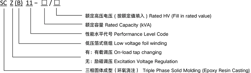
Model and Meaning
Product Features
- Low loss,energy-saving with low operating cost
- Flame-retardant, fire & explosion proof, eco-friendly
- Excellent moisture resistance and heat dissipation
- Low partial discharge, low noise, maintenance-free
- High mechanical strength, strong short-circuit resistance, long service life
Technical Parameters
| Rated Capacity (kVA) | Voltage Combinationed Tap Range | Vector Group Symbol | No-load Loss (W) | Load Loss(W) | No-load Current % | Impedance Voltage % | ||||
| HV(kV) | HV Tap Range % | LV(kV) | 130℃(B)100℃ | 155℃(F)120℃ | 180℃(H)145℃ | |||||
| 30 | 6 6.3 6.6 10 10.5 11 |
±2×2.5 ±5 |
0.4 | Dyn11 Yyn0 |
170 | 670 | 710 | 760 | 2 | 4.0 |
| 50 | 240 | 940 | 1000 | 1070 | 2 | |||||
| 80 | 330 | 1290 | 1380 | 1480 | 1.5 | |||||
| 100 | 360 | 1480 | 1570 | 1690 | 1.5 | |||||
| 125 | 420 | 1740 | 1850 | 1980 | 1.3 | |||||
| 160 | 480 | 2000 | 2130 | 2280 | 1.3 | |||||
| 200 | 550 | 2370 | 2530 | 2710 | 1.1 | |||||
| 250 | 640 | 2590 | 2760 | 2690 | 1.1 | |||||
| 315 | 790 | 3270 | 3470 | 3730 | 1 | |||||
| 400 | 880 | 3750 | 3990 | 4280 | 1 | |||||
| 500 | 1040 | 4590 | 4880 | 5230 | 1 | |||||
| 630 | 1200 | 5530 | 5880 | 6290 | 0.85 | |||||
| 630 | 1170 | 5610 | 5960 | 6400 | 0.85 | 6.0 | ||||
| 800 | 1360 | 6550 | 6960 | 7460 | 0.85 | |||||
| 1000 | 1590 | 7650 | 8130 | 8760 | 0.85 | |||||
| 1250 | 1880 | 9100 | 9690 | 10300 | 0.85 | |||||
| 1600 | 2200 | 11000 | 11700 | 12500 | 0.85 | |||||
| 2000 | 2740 | 13600 | 14400 | 15500 | 0.7 | |||||
| 2500 | 3240 | 16100 | 17100 | 18400 | 0.7 | |||||
| 1600 | 2200 | 12200 | 12900 | 13900 | 0.85 | 8.0 | ||||
| 2000 | 2740 | 15000 | 15900 | 17100 | 0.7 | |||||
| 2500 | 3240 | 17700 | 18800 | 20200 | 0.7 | |||||
SC(ZB)13 Series 6kV~10kV Class Off-Circuit Tap-Changing Distribution Dry-type Transformers
| Rated Capacity (kVA) | Voltage Combinationed Tap Range | Vector Group Symbol | No-load Loss (W) | load Loss (W) | No-load Current % | Impedance Voltage % | ||||
| HV(kV) | HV Tap Range % | LV(kV) | 130℃(B)100℃ | 155℃(F)120℃ | 180℃(H)145℃ | |||||
| 30 | 6 6.3 6.6 10 10.5 11 |
±2×2.5 ±5 |
0.4 | Dyn11 Yyn0 |
135 | 605 | 640 | 685 | 2 | 4.0 |
| 50 | 195 | 845 | 900 | 965 | 2 | |||||
| 80 | 265 | 1160 | 1240 | 1330 | 1.5 | |||||
| 100 | 290 | 1330 | 1410 | 1520 | 1.5 | |||||
| 125 | 340 | 1565 | 1660 | 1780 | 1.3 | |||||
| 160 | 385 | 1800 | 1910 | 2050 | 1.3 | |||||
| 200 | 445 | 2135 | 2270 | 2440 | 1.1 | |||||
| 250 | 515 | 2330 | 2480 | 2660 | 1.1 | |||||
| 315 | 635 | 2940 | 3120 | 3350 | 1 | |||||
| 400 | 705 | 3370 | 3590 | 3850 | 1 | |||||
| 500 | 835 | 4130 | 4390 | 4700 | 1 | |||||
| 630 | 965 | 4970 | 5290 | 5660 | 0.85 | |||||
| 630 | 935 | 5050 | 5360 | 5760 | 0.85 | 6.0 | ||||
| 800 | 1090 | 5890 | 6260 | 6710 | 0.85 | |||||
| 1000 | 1270 | 6880 | 7310 | 7880 | 0.85 | |||||
| 1250 | 1500 | 8190 | 8720 | 9330 | 0.85 | |||||
| 1600 | 1760 | 9940 | 10500 | 11300 | 0.85 | |||||
| 2000 | 2190 | 12200 | 13000 | 14000 | 0.7 | |||||
| 2500 | 2590 | 14500 | 15400 | 16600 | 0.7 | |||||
| 1600 | 1760 | 11000 | 11600 | 12500 | 0.85 | |||||
| 2000 | 2190 | 13500 | 14300 | 15400 | 0.7 | |||||
| 2500 | 2590 | 15900 | 17000 | 18200 | 0.7 | |||||
Note: The load losses listed in the table are measured values for different insulation systems at the reference temperatures given in parentheses (specified in GB/T 1094.1-11). For load losses under other insulation systems not given in this table, corresponding conversion shall be carried out based on their respective reference temperatures, using the data of the 155 ℃ (Class F) insulation system as the benchmark.
SC(ZB)12 Series Energy Efficiency Class 3 6kV, 10kV Off-CCircuit Tap-Changing Distribution Dry-type Transformers
| Rated Capacity (kVA) | Voltage Combinationed Tap Range | Vector Group Symbol | No-load Loss (W) | Load Loss(W) | No-load Current % | Impedance Voltage % | ||||
| HV(kV) | HV Tap Range % | LV(kV) | 130℃(B)100℃ | 155℃(F)120℃ | 180℃(H)145℃ | |||||
| 30 | 6 6.3 6.6 10 10.5 11 |
±2×2.5 ±5 |
0.4 | Dyn11 Yyn0 |
150 | 670 | 710 | 760 | 2.0 | 4.0 |
| 50 | 215 | 940 | 1000 | 1070 | 2.0 | |||||
| 80 | 295 | 1290 | 1380 | 1480 | 1.5 | |||||
| 100 | 320 | 1480 | 1570 | 1690 | 1.5 | |||||
| 125 | 375 | 1740 | 1850 | 1980 | 1.3 | |||||
| 160 | 430 | 2000 | 2130 | 2280 | 1.3 | |||||
| 200 | 495 | 2370 | 2530 | 2710 | 1.1 | |||||
| 250 | 575 | 2590 | 2760 | 2960 | 1.1 | |||||
| 315 | 705 | 3270 | 3470 | 3730 | 1.0 | |||||
| 400 | 785 | 3750 | 3990 | 4280 | 1.0 | |||||
| 500 | 930 | 4590 | 4880 | 5230 | 1.0 | |||||
| 630 | 1070 | 5530 | 5880 | 6290 | 0.85 | |||||
| 630 | 1040 | 5610 | 5960 | 6400 | 0.85 | 6.0 | ||||
| 800 | 1215 | 6550 | 6960 | 7460 | 0.85 | |||||
| 1000 | 1415 | 7650 | 8130 | 8760 | 0.85 | |||||
| 1250 | 1670 | 9100 | 9690 | 10370 | 0.85 | |||||
| 1600 | 1960 | 11050 | 11730 | 12580 | 0.85 | |||||
| 2000 | 2440 | 13600 | 14450 | 15560 | 0.7 | |||||
| 2500 | 2880 | 16150 | 17170 | 18450 | 0.7 | |||||
SC(ZB)14 Series Energy Efficiency Class 2 6kV, 10kV Off-Circuit Taap-Changing Distribution Dry-type Transformers
| Rated Capacity (kVA) | Voltage Combinationed Tap Range | Vector Group Symbol | No-load Loss (W) | Load Loss(W) | No-load Current % | Impedance Voltage % | ||||
| HV(kV) | HV Tap Range % | LV(kV) | 130℃(B)100℃ | 155℃(F)120℃ | 180℃(H)145℃ | |||||
| 30 | 6 6.3 6.6 10 10.5 11 |
±2×2.5 ±5 |
0.4 | Dyn11 Yyn0 |
150 | 670 | 710 | 760 | 2 | 4.0 |
| 50 | 215 | 940 | 1000 | 1070 | 2 | |||||
| 80 | 295 | 1290 | 1380 | 1480 | 1.5 | |||||
| 100 | 320 | 1480 | 1570 | 1690 | 1.5 | |||||
| 125 | 375 | 1740 | 1850 | 1980 | 1.3 | |||||
| 160 | 430 | 2000 | 2130 | 2280 | 1.3 | |||||
| 200 | 495 | 2370 | 2530 | 2710 | 1.1 | |||||
| 250 | 575 | 2590 | 2760 | 2960 | 1.1 | |||||
| 315 | 705 | 3270 | 3470 | 3730 | 1 | |||||
| 400 | 785 | 3750 | 3990 | 4280 | 1 | |||||
| 500 | 930 | 4590 | 4880 | 5230 | 1 | |||||
| 630 | 1070 | 5530 | 5880 | 6290 | 0.85 | |||||
| 630 | 1040 | 5610 | 5960 | 6400 | 0.85 | 6.0 | ||||
| 800 | 1215 | 6550 | 6960 | 7460 | 0.85 | |||||
| 1000 | 1415 | 7650 | 8130 | 8760 | 0.85 | |||||
| 1250 | 1670 | 9100 | 9690 | 10370 | 0.85 | |||||
| 1600 | 1960 | 11050 | 11730 | 12580 | 0.85 | |||||
| 2000 | 2440 | 13600 | 14450 | 15560 | 0.7 | |||||
| 2500 | 2880 | 16150 | 17170 | 18450 | 0.7 | |||||
Notes:① The load losses listed in the table are values for different insulation systems at the reference temperatures given in parentheses (specified in GB/T 1094.11). For load losses of other insulation systems not covered in this table, corresponding conversion shall be conducted based on their respective reference temperatures, with the data of the 155 ℃(Class F) insulation system taken as the benchmark.
② The no-load losses listed in the table meet the requirements for energy efficiency Class 3 specified in Table 2 of GB 20052-2020.
SC(ZB)18 Series Energy Efficiency Class 1 6kV, 10kv Off-Circuit Tap-Changing Distribution Dry-type Transformers
| Rated Capacity (kVA) | Voltage Combinationed Tap Range | Vector Group Symbol | No-load Loss (W) | Load Loss(W) | No-load Current % | Impedance Voltage % | ||||
| HV(kV) | HV Tap Range % | LV(kV) | 130℃(B)100℃ | 155℃(F)120℃ | 180℃(H)145℃ | |||||
| 30 | 6 6.3 6.6 10 10.5 11 |
±2×2.5 ±5 |
0.4 | Dyn11 Yyn0 |
105 | 605 | 640 | 685 | 2.0 | 4.0 |
| 50 | 155 | 845 | 900 | 965 | 2.0 | |||||
| 80 | 210 | 1160 | 1240 | 1330 | 1.5 | |||||
| 100 | 230 | 1330 | 1415 | 1520 | 1.5 | |||||
| 125 | 270 | 1565 | 1665 | 1780 | 1.3 | |||||
| 160 | 310 | 1800 | 1915 | 2050 | 1.3 | |||||
| 200 | 360 | 2135 | 2275 | 2440 | 1.1 | |||||
| 250 | 415 | 2330 | 2485 | 2665 | 1.1 | |||||
| 315 | 510 | 2945 | 3125 | 3355 | 1.0 | |||||
| 400 | 570 | 3375 | 3590 | 3850 | 1.0 | |||||
| 500 | 670 | 4130 | 4390 | 4705 | 1.0 | |||||
| 630 | 775 | 4975 | 5290 | 5660 | 0.85 | |||||
| 630 | 750 | 5050 | 5365 | 5760 | 0.85 | 6.0 | ||||
| 800 | 875 | 5895 | 6265 | 6715 | 0.85 | |||||
| 1000 | 1020 | 6885 | 7315 | 7885 | 0.85 | |||||
| 1250 | 1205 | 8190 | 8720 | 9335 | 0.85 | |||||
| 1600 | 1415 | 9945 | 10555 | 11320 | 0.85 | |||||
| 2000 | 1760 | 12240 | 13005 | 14005 | 0.7 | |||||
| 2500 | 2080 | 14535 | 15445 | 16605 | 0.7 | |||||
Notes:① The load losses listed in the table are values for different insulation systems at the reference temperatures given in parentheses (specified in GB/T 1094.1-1). For load losses of other insulation systems not covered in this table, corresponding conversion shall be conducted based on their respective reference temperatures, with the data of the 155℃ (Class F) insulation system taken as the benchmark.
② The no-load losses listed in the table meet the requirements for energy efficiency Class 3 specified in Table 2 of GB 20052-2020.
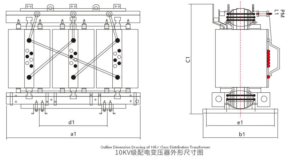
Outline Dimension Drawing