
How to test voltage transformer means confirming an instrument VT/PT with nameplate review, insulation resistance, polarity, and a primary-side ratio check—not a 24 V HVAC control-transformer multimeter recipe—so buyers demand the right evidence before trusting the secondary signal.
Search results often answer the same phrase with continuity beeps and live 24 V checks on control transformers. Potential transformer testing for meters and relays follows a different sequence: visual and nameplate confirmation, insulation resistance, polarity, then a primary-side voltage transformer ratio test, with burden and secondary grounding kept inside project limits. The sections below separate those product classes, walk the acceptance checks, flag the secondary-backfeed hazard, list paperwork buyers can request, and show one indoor epoxy pathway when metering and protection classes both matter.
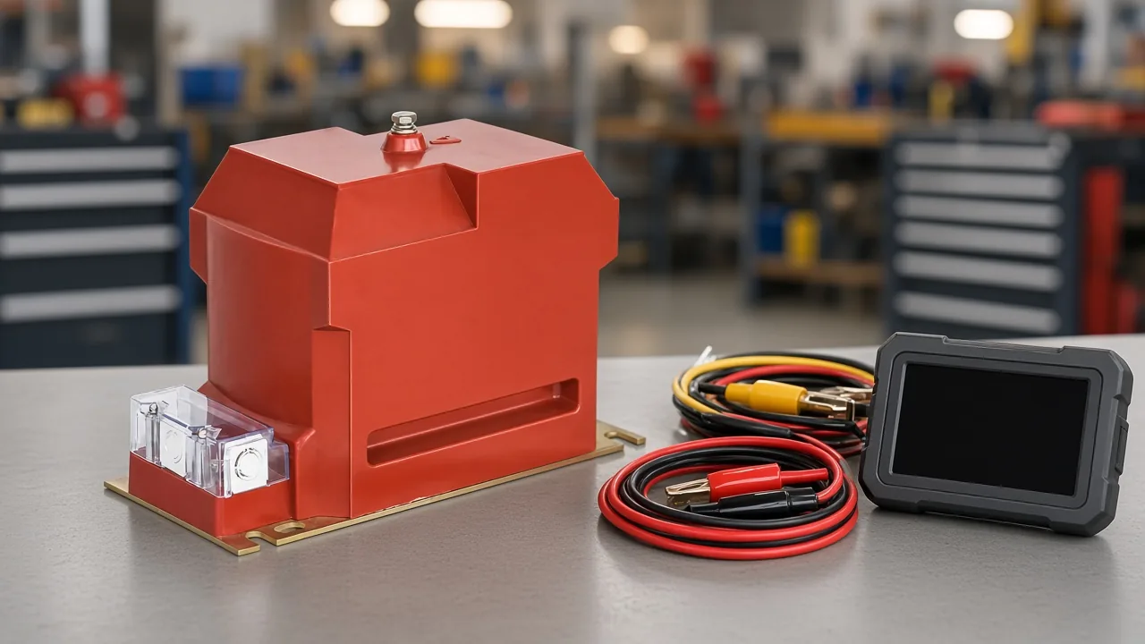
Instrument voltage transformers versus power and control transformers
This coverage is for instrument voltage transformers used with meters and relays—not HVAC control transformers or power-transformer site commissioning.
An instrument voltage transformer (VT/PT) is a parallel-connected transformer that steps system voltage down for meters and relays. In plain terms, it is the small transformer that feeds instruments—not the main power transformer that moves load current, and not the HVAC control transformer that supplies thermostat circuits.
Many online “test a voltage transformer” recipes measure cold continuity, then check about 21–28 V on a 24 V control secondary. That workflow answers a different product class. Voltage transformer testing for metering and protection starts from the nameplate ratio, accuracy class, and secondary circuit the project will trust.
Battery-charger DIY and audio output-transformer checks also sit outside this scope. If the unit under discussion is an MV indoor epoxy VT for switchgear or a metering cabinet, stay with the instrument-VT checklist below.
Core checks buyers should expect on a voltage transformer
After nameplate and visual review, expect insulation resistance, polarity, and turns-ratio checks.
Commissioning teams receiving an indoor VT usually start with a cold walk-around: cracked epoxy, damaged terminals, missing seals, and a nameplate that matches the purchase order for ratio, class, and rated voltage. Only then does potential transformer testing move into electrical checks.
An insulation resistance test uses a megohmmeter between windings and to ground with windings isolated as the procedure requires. Educational practice often cites megger classes in the 500–5000 V range—for example about 2.5 kV on a 6.6 kV VT class and about 5 kV on a 132 kV VT class—while accept values stay with the manufacturer or project criteria, not a universal floor for every SKU.
A VT polarity test confirms that marked primary and secondary terminals still agree. The common field method is a low-voltage DC flick—often a 9–12 V battery—with a milliammeter deflection that matches the marked relationship; related AC methods appear when the procedure calls for them.
A turns ratio / voltage ratio test applies reduced AC on the primary, measures the secondary, and compares the result to the nameplate. Dielectric withstand on the primary with secondaries grounded, when the project specifies it, is a deeper factory- or lab-style step rather than a casual bench shortcut.
| Check | Purpose | Buyer decision |
|---|---|---|
| Visual / nameplate | Confirm identity, damage, and printed ratio/class | Reject or quarantine before electrical work if the plate or body fails the order |
| Insulation resistance | Show windings and ground paths are dry and intact | Hold energization until IR axes meet OEM/project criteria |
| Polarity (flick or AC) | Confirm marked terminal relationship | Fix landings before directional or differential protection depends on the VT |
| Turns / voltage ratio | Compare measured Vp/Vs behavior to the nameplate | Treat continuity alone as incomplete; demand ratio evidence |
From the field: Continuity alone finds open windings; crews still call for insulation testing and a ratio measurement before calling a transformer “good” for service — practitioner PT burden/ratio framing on Electrician Talk.
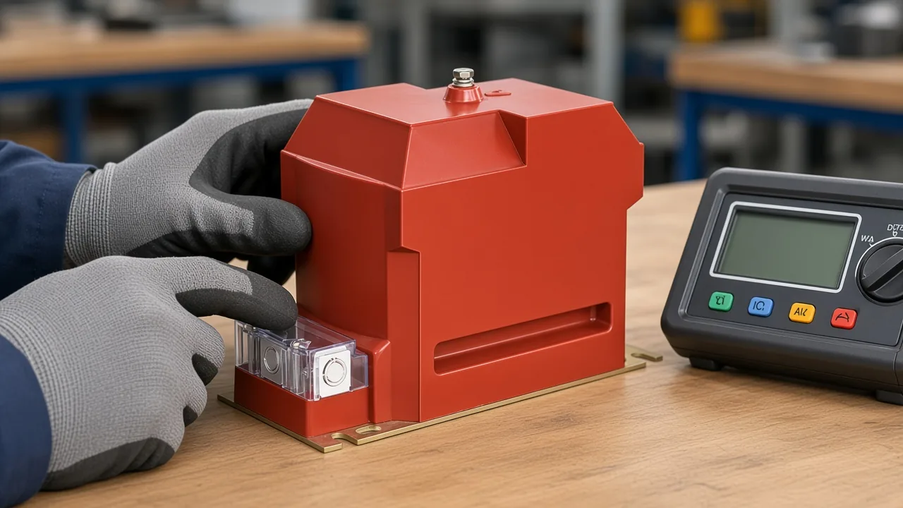
Safe ratio practice and mistakes that invalidate the check
Inject reduced AC on the primary only; continuity alone is not acceptance; never energize the secondary to step into the primary.
A voltage transformer ratio test is valid when the injection stays on the primary side and the secondary reading is compared to the printed ratio. Some bench habits try a reverse feed—energizing the small secondary terminals to “see” high voltage on the primary. That reverse feed can impress hazardous voltage on the primary and has destroyed meters when people treated adapter secondaries as harmless.
Important: Never apply a test voltage to the VT secondary with the primary accessible—the turns ratio can produce hazardous primary voltage.
Secondary injection for phasing or relay work is a different, controlled procedure that isolates paths so the primary is not back-fed. It is not a substitute for a casual multimeter “ratio up” trick. Warehouse-aged PTs also fail ratio against project criteria after long storage, so acceptance still needs manufacturer limits and history context—not a one-line good/bad beep.
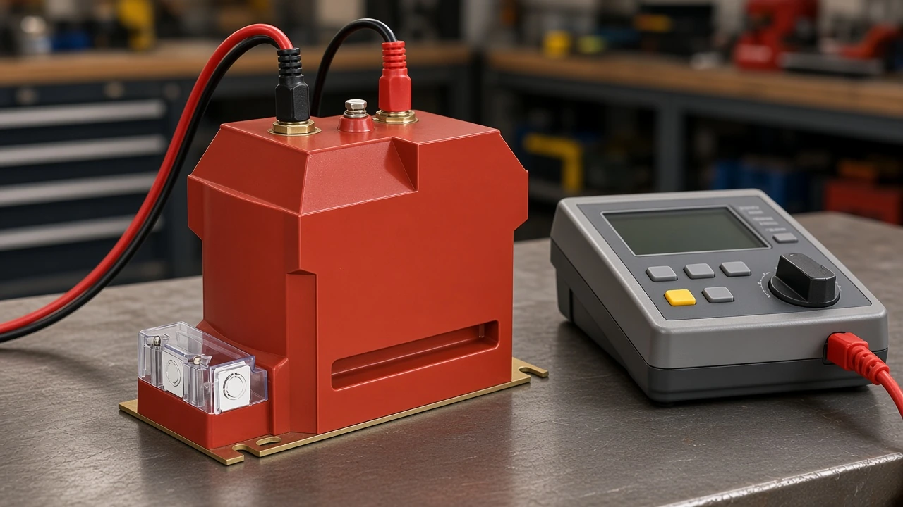
Burden, accuracy class, and secondary grounding awareness
Keep connected burden inside the nameplate rating and confirm secondary grounding matches the project single-point plan.
Burden is the connected secondary VA of meters and relays relative to the nameplate rating. Accuracy class and burden interact: if the instruments overload the secondary VA, metering can leave its accuracy class even when a light-load ratio look correct.
Single-point secondary grounding means the secondary earth is bonded at one documented point per project practice. Scattered multi-point earths on the same secondary circuit confuse fault paths and make troubleshooting harder. Confirm the drawing’s ground location before signing off.
Secondary circuits may be open on a VT in ways a CT secondary must not be left open under load—but that difference does not excuse wrong polarity, overloaded burden, or reverse energization. Keep the metering and protection burdens inside printed limits when accuracy matters.
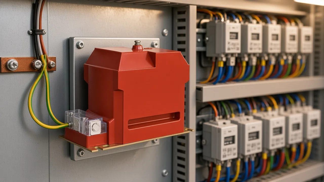
What evidence and paperwork to request from the VT supplier
Ask for nameplate data and available insulation/ratio records—only the marks and records the supplier publishes with the unit.
Buyers preparing a receiving or commissioning pack should request the printed nameplate fields (ratio, accuracy/protection class, rated voltage, burden), any routine insulation-resistance and ratio records the supplier ships with the lot, and the manufacturer’s acceptance limits for those checks. Where a project needs deeper dielectric or excitation evidence, request only the factory records that ship with that lot or that the supplier can produce for the SKU.
If units sat in a warehouse for years, ask for storage history and the OEM ratio tolerance before treating every deviation as a field wiring fault. Treat unpublished listing marks as absent from the pack—ask the supplier to confirm what ships with the unit rather than assuming a mark exists.
Which JOHNN indoor VT fits a metering and protection testing pathway?
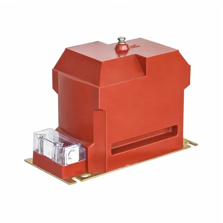
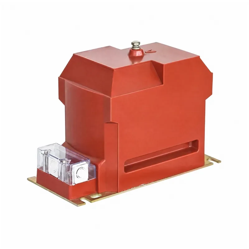
The JDZX10-3/6/10 voltage transformer is the indoor path with published metering accuracy class / 6P protection class columns plus insulation-level rows; JDZ10 / JDZ-Q / JDZ(J) / JDZC remain alternatives when their drivers dominate.
After IR, polarity, and primary-side ratio discipline are clear, indoor switchgear, metering cabinets, and distribution panels need a live epoxy VT example. Open the JDZX10 indoor voltage transformer when the project needs metering accuracy classes and a 6P protection output on the same indoor family, with published insulation-level rows a test plan can discuss.
JDZX10-3/6/10 covers indoor 3/6/10 kV systems. Published secondary output classes include 0.2, 0.5, Class 1, Class 3, and 6P, with a maximum output example of 200 VA on the parameter table. Rated insulation levels print as 3.6/25/40, 7.2/32/60, and 12/42/75 kV.
| Project driver | Prefer | Why it fits |
|---|---|---|
| Metering classes plus 6P protection column on one indoor epoxy body | JDZX10-3/6/10 | Aligns a metering-and-protection test plan to published class and insulation rows |
| High-accuracy metering ratios without needing the JDZX 6P column | JDZ10-3/6/10(Q) | Published ratios such as 3000/100, 6000/100, and 10000/100 for metering-led jobs |
| Simpler two-winding or dual-secondary JDZ-Q row | JDZ-3/6/10Q | Dual-secondary rows such as 10000/100/100 when the panel layout is simpler |
| Three-winding / open-delta style secondary arrangements | JDZ(J)-3/6/10Q | Three-winding arrangements when the drawing needs that secondary pattern |
| Auxiliary 220 V secondary duty on the nameplate | JDZC-6/10 | Ratios such as 6000/100/220 and 10000/100/220 when the aux secondary is required |
Browse the Voltage Transformers hub when another indoor nameplate pattern fits better. Instrument transformer practice often sits under the IEC 61869 family by name; match the project drawing and the printed cells on the selected product page.
What stays outside this voltage transformer testing page
Testing-equipment catalogs, VT types and selection depth, wiring diagrams, and CT deep-dives belong on other pages.
Instrument-transformer analyzer buy-guides, full VT type taxonomies, wiring-diagram galleries, and current-transformer polarity labs belong in dedicated articles. After IR, polarity, and primary-side ratio are clear—and one indoor JDZX pathway when metering and protection classes both apply—those deeper catalogs can wait.
FAQ
How do you test a voltage transformer (VT/PT)?
Confirm the nameplate and body, record insulation resistance on the required axes, run a polarity check, then perform a primary-side ratio measurement and document the results. Add burden and secondary-grounding checks when metering accuracy and project drawings require them.
Is testing a voltage transformer the same as testing a 24 V HVAC transformer?
No. HVAC control-transformer recipes target thermostat secondaries; instrument VT/PT acceptance targets meters and relays on a printed MV ratio and class. Treat the 24 V multimeter workflow as a different product class.
Can I use only a multimeter continuity check?
No. Continuity can find an open winding, but it does not prove insulation integrity or ratio. Insulation resistance and a primary-side ratio check remain part of acceptance language for instrument VTs.
Why must I not energize the VT secondary during ratio checks?
The turns ratio can impress hazardous voltage on the primary if the secondary is driven while the primary is accessible. Keep ratio injection on the primary; treat reverse feed as a serious hazard.
What is a polarity test on a VT?
A VT polarity test confirms that marked primary and secondary terminals still agree, commonly with a low-voltage DC flick and meter deflection, or with an AC method the procedure allows. Fix landings before directional protection depends on the VT.
Does ratio accuracy depend on burden?
Yes. Connected secondary VA above the rated burden can push metering outside its accuracy class even when a light-load ratio looks acceptable. Keep instruments inside the printed burden.
What should a buyer ask the VT supplier to provide?
Request nameplate data, available insulation and ratio records, and the manufacturer’s acceptance limits. Ask only for the marks and records the supplier publishes with the unit.
Where does JOHNN JDZX10 fit after you understand the tests?
JDZX10 is the indoor epoxy example when metering classes and a 6P protection column plus published insulation-level rows must align to one test plan. Choose JDZ10, JDZ-Q, JDZ(J), or JDZC when high-accuracy-only ratios, simpler dual-secondary rows, three-winding arrangements, or a 220 V auxiliary secondary drive the choice instead.