
Current transformer wiring means installing the CT with source-side polarity marks, landing S1/S2 into a closed meter or relay burden, and never leaving the secondary open while primary current flows—so buyers and panel builders treat shorting and polarity as pre-service checks, not afterthoughts.
Wrong polarity flips power or energy sense. An open secondary under load is a different failure: dangerous voltage on the instrument leads. The sections below walk the CT connection checklist, the conventional-CT versus low-voltage-output-sensor contrast, grounding notes, a light three-phase pointer, and one indoor epoxy pathway for switchgear work.
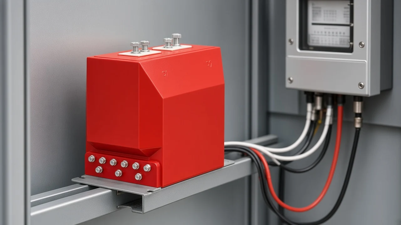
What current transformer wiring covers before service
It covers primary orientation, secondary landings into a closed burden, and polarity consistency—not selection math or a diagram gallery.
A Current transformer (CT) scales line current so meters and relays can read it safely. In practice, the Primary conductor / window is the power path through the core (or a series primary), and the Secondary terminals S1/S2 are the small landings that feed instruments.
How to connect a current transformer for service readiness is a short loop: mount with documented direction, land the secondary into the intended burden, and keep that loop closed whenever primary current can flow. Burden is the connected meter/relay load—keep the total inside the CT rating printed for that core.
Panel builders who ask which secondary norm the instruments expect are already inside this scope. Ratio picking and type catalogs need their own selection or types guides.
Traditional CT secondaries versus low-voltage output sensors
Conventional current-output CT secondaries and low-voltage output sensors are different landing problems—do not copy shorting habits blindly across both.
Instrument education commonly builds conventional CT secondary circuits around 1 A or 5 A inputs. Those loops expect a closed path into ammeters, transducers, or relays, with shorting-block discipline when a device is removed.
A low-voltage output sensor style that outputs a low voltage signal—often discussed as a 0.333 V-class sensor in metering catalogs—is a different landing problem. Its signal cable and input module are not interchangeable with a 1 A/5 A CT secondary circuit, and the “always short the CT” habit does not transfer as a blind rule.
When a spec sheet mixes both languages on one bill of materials, treat each device by its published secondary type before you choose shorting hardware.
Polarity orientation for primary and secondary marks
Match P1/H1 (or arrow) toward source and land S1/X1 to the instrument polarity terminal per the drawing.
Polarity orientation pairs nameplate marks so power, energy, and directional relays sense the right way. Install so P1 or H1 (or the molded arrow) faces the source or line side; P2 or H2 faces the load.
On the secondary, S1 or X1 is the polarity lead that lands on the instrument’s polarity terminal; S2 or X2 completes the pair. Some drawings still use k/l marks for the same idea.
If metering shows negative energy after install, re-check P1/P2 and S1/S2 before replacing the meter. Simple ammeters may care less about polarity; wattmeters, energy meters, and many relays do. This checklist stops at orientation—field polarity-test labs need a dedicated test procedure.
Keep the secondary closed: shorting before disconnect
Never leave a CT secondary open under load; short before removing a meter or relay; clear maintenance shorts before protection returns to service.
An open secondary hazard appears when primary current still flows while the secondary is open-circuit. Educational sources warn that the open secondary can produce high voltage—on the order of several kilovolts for some CTs—with arcing, personnel risk, and possible accuracy damage.
| Secondary state | When it is acceptable | What to do |
|---|---|---|
| Burden connected | Normal metering or protection service | Leave the instrument loop closed |
| Shorted for maintenance | Meter or relay removed under primary current risk | Apply shorting block / shorting screws first, then disconnect |
| Open under load | Never acceptable in service | Stop work; restore a short or reconnect the burden |
CT secondary shorting is the temporary deliberate short across the secondary while you pull a device. Short first, then disconnect. When protection returns to service, clear those shorts so relays are not left defeated.
From the field: Leaving a CT secondary open under load is treated as unacceptable—high voltage, arcing, and accuracy harm are the reasons crews keep teaching short-before-disconnect — TestGuy forum on shorting a CT secondary.
Important: Maintenance shorts left in place can defeat protection when the board returns to service—remove shorting screws after the meter or relay is landed again.
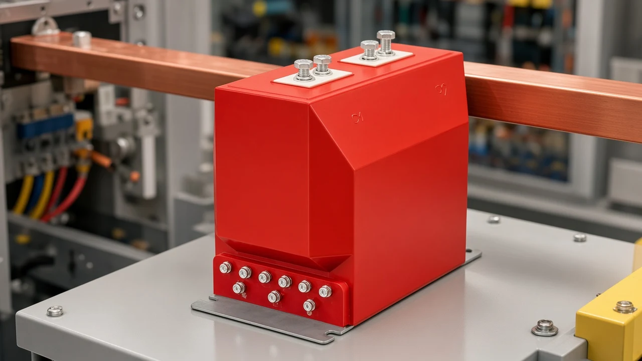
Secondary earthing and unused cores on the drawing
Use a documented single grounding point when required; unused cores are shorted—follow the protection/metering drawing.
Secondary earthing is a project-drawing rule, not a free-hand habit. When secondaries are galvanically tied, education sources point to one grounding point rather than many scattered bonds. Ground S1 or S2 only where the drawing says.
Unused cores on multi-ratio or multi-core CTs are shorted—commonly on the highest ratio taps in IEC-oriented teaching—and unused taps are left open. Metering vs protection cores on the same body still share that closed-secondary discipline even when their accuracy classes differ.
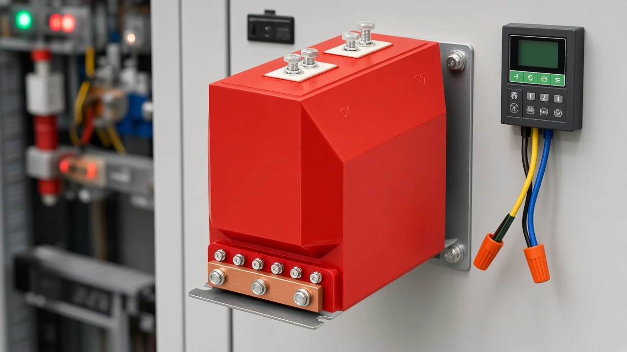
Three-phase connection pointers without a types catalog
Boards usually follow a documented star or two-CT scheme—stay on the drawing rather than inventing a scheme from a random gallery.
Three-phase panels often use three CTs in a star/wye with a common secondary neutral, or a two-CT incomplete-star / V arrangement where the drawing allows it. Keep polarity and closed-secondary rules intact on whichever scheme the protection engineer already chose.
Do not treat a random online diagram pack as a substitute for the project one-line. Configuration catalogs and image galleries are separate articles.
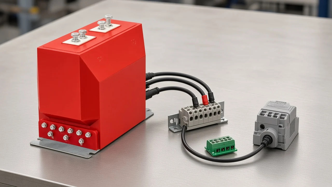
Keep the conventional current-output loop and the low-voltage sensor landing on separate checklists even when both appear on the same three-phase board.
Which JOHNN indoor CT fits a switchgear wiring pathway?
LZZBJ9-10C1 is the indoor epoxy CT for switchgear and metering cabinets; choose outdoor LZZW-10Q or LZW32 when the install is outdoor or pole-mounted.
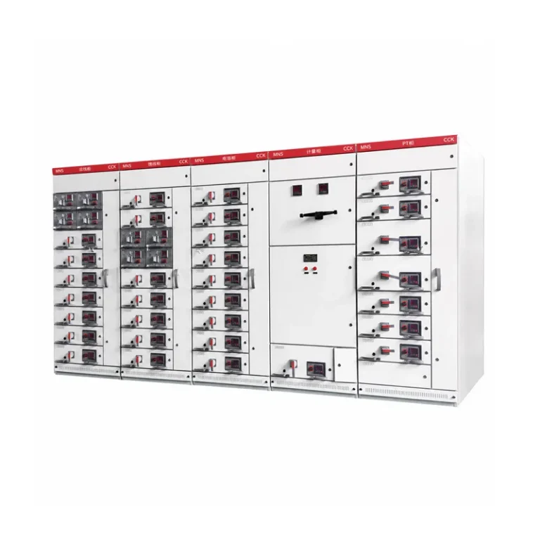
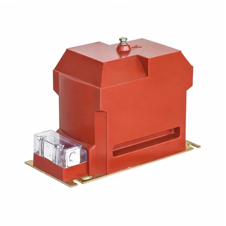
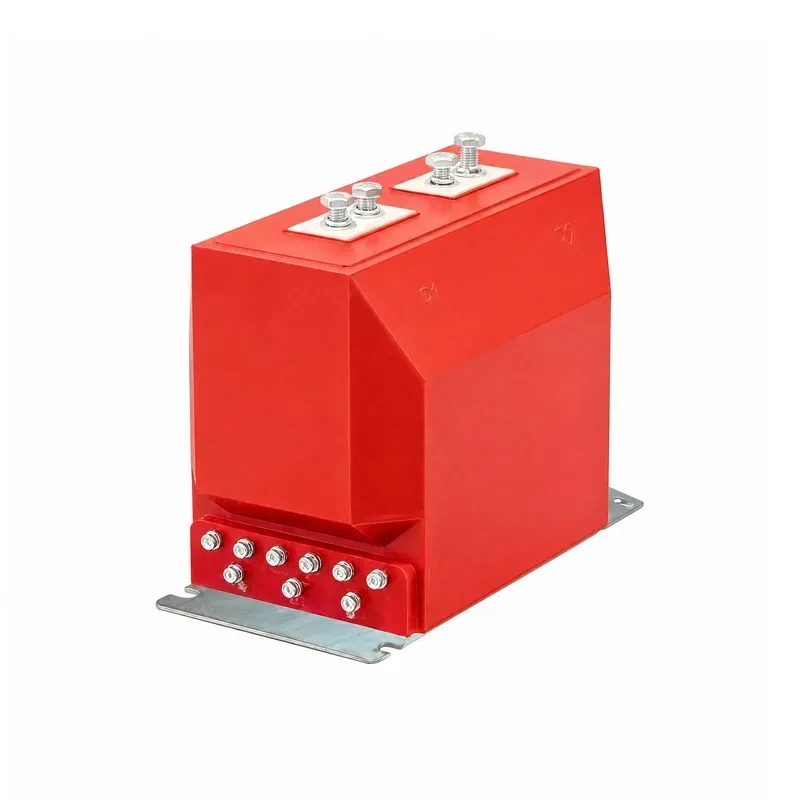
After polarity, closed-secondary, and shorting discipline are clear, indoor switchgear or metering-cabinet work needs a live epoxy CT example. Open the LZZBJ9-10C1 indoor current transformer when the job is indoor medium-voltage current measurement and protection signal conversion for switchgear, metering cabinets, and distribution panels.
LZZBJ9-10C1 is published as a high-accuracy indoor current transformer for 10 kV medium-voltage systems. Printed combination headers include 0.2S/10P10, 0.5S/10P10, 0.2/10P10, and 0.5/10P10, with secondary output columns on the combination row pattern including 10 VA / 10 VA / 15 VA—cells a wiring plan can align to metering and protection cores on the same body.
| Install class | Prefer | Why |
|---|---|---|
| Indoor switchgear / metering cabinet / distribution panel | LZZBJ9-10C1 | Indoor epoxy pathway that matches this wiring checklist |
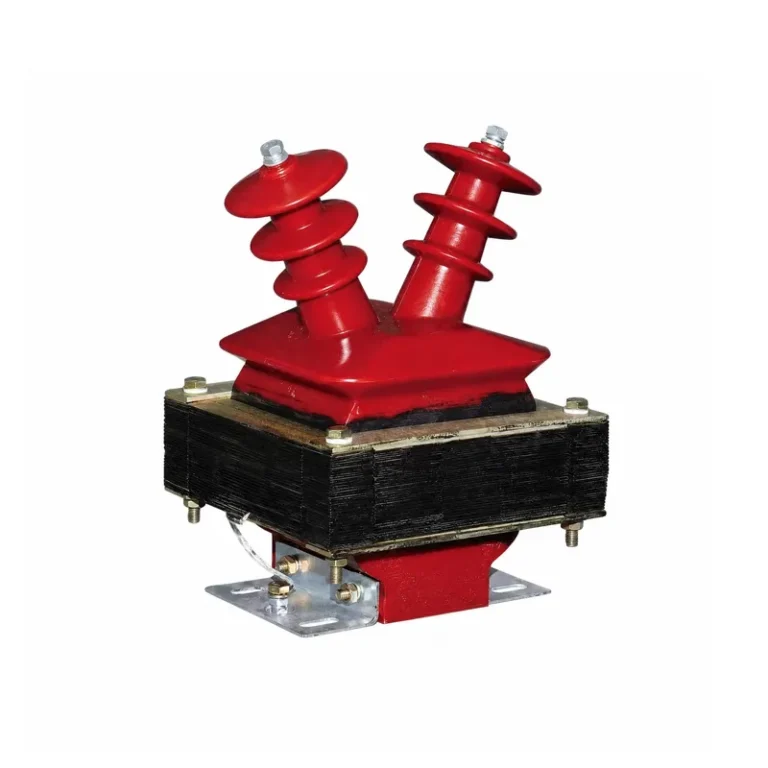
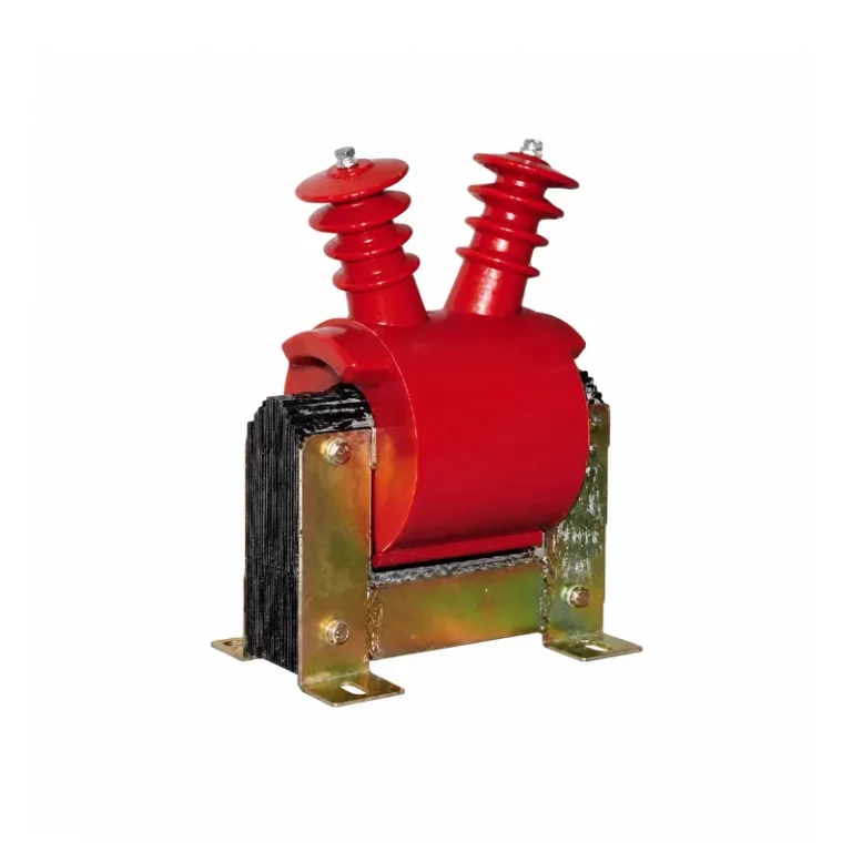
| Outdoor, pole-mounted, or overhead distribution | LZZW-10Q / LZW32 | Outdoor or pole duty—honest alternatives when the install leaves the indoor cabinet |
Browse the Current Transformers hub if outdoor or pole duty dominates. Instrument transformer practice often sits under the IEC 61869 family by name; match the project drawing and the printed PDP cells.
What stays outside this wiring page
Wiring-diagram galleries, types of CT, selection sizing, and polarity-test labs belong elsewhere.
This checklist covers connection practice, shorting discipline, polarity orientation, and the indoor LZZBJ9 pathway. Diagram galleries, CT types, sizing guides, and polarity-test labs belong in dedicated articles; CT-versus-VT pairing sits with instrument-transformer pairing guidance, not this connection walkthrough.
FAQ
How is a CT connected?
The primary path is the conductor through the CT window (or a series primary). Land Secondary terminals S1/S2 to the meter or relay with polarity matching the drawing, and keep the secondary closed into its burden whenever primary current can flow.
How do you install a CT with correct direction?
Face P1/H1 or the molded arrow toward the source/line side and P2/H2 toward the load. Match the nameplate marks to the protection or metering drawing before you torque the last secondary lead.
How do you connect CT secondary wires?
Land S1/S2 (or k/l, or X1/X2) on the instrument terminals per the drawing. Stay inside the CT’s rated burden, and build conventional loops around the 1 A or 5 A instrument norms the panel expects.
Why must you never open a CT secondary under load?
An open secondary with primary current flowing can produce dangerous high voltage, arcing, and possible CT damage. Keep a proper burden connected or apply a deliberate short.
When do you use a CT shorting block?
Use shorting block / shorting screws before you remove or isolate a meter or relay under possible primary current. Clear those shorts after the device is reconnected so protection is not left defeated.
What happens if CT polarity is reversed?
Swapped S1/S2 or reversed P1/P2 can show negative or false power and energy readings and can upset directional relay sense. Re-check marks before blaming the instrument.
What is a “CT wire”?
In shop talk, a “CT wire” usually means the secondary leads to instruments—not the primary power conductor through the window.
Where does JOHNN LZZBJ9-10C1 fit after wiring basics?
LZZBJ9-10C1 is the indoor 10 kV epoxy example for switchgear, metering cabinets, and distribution panels after the wiring checklist. Choose outdoor LZZW-10Q / LZW32 options only when the install is outdoor or pole-mounted.