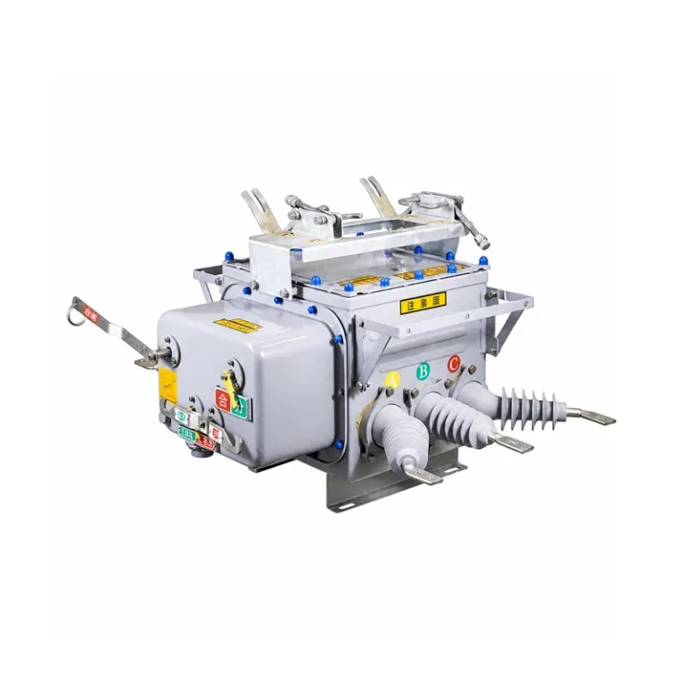
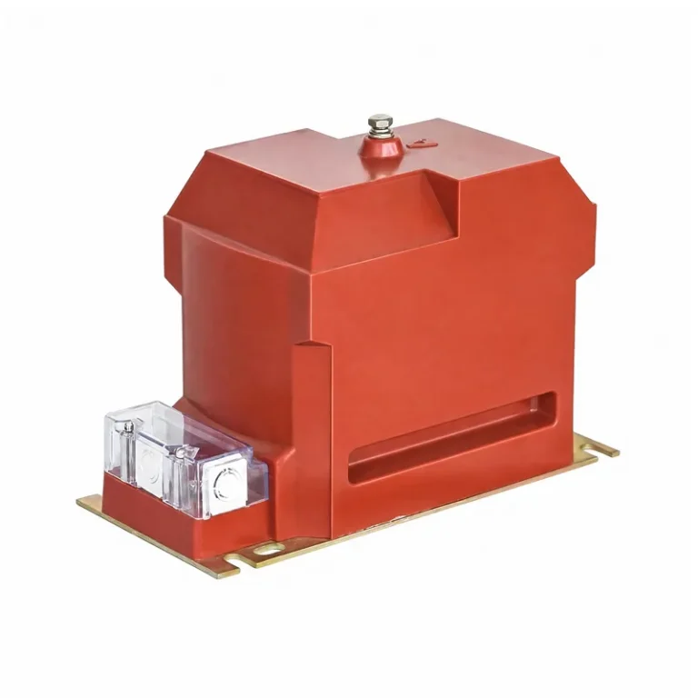
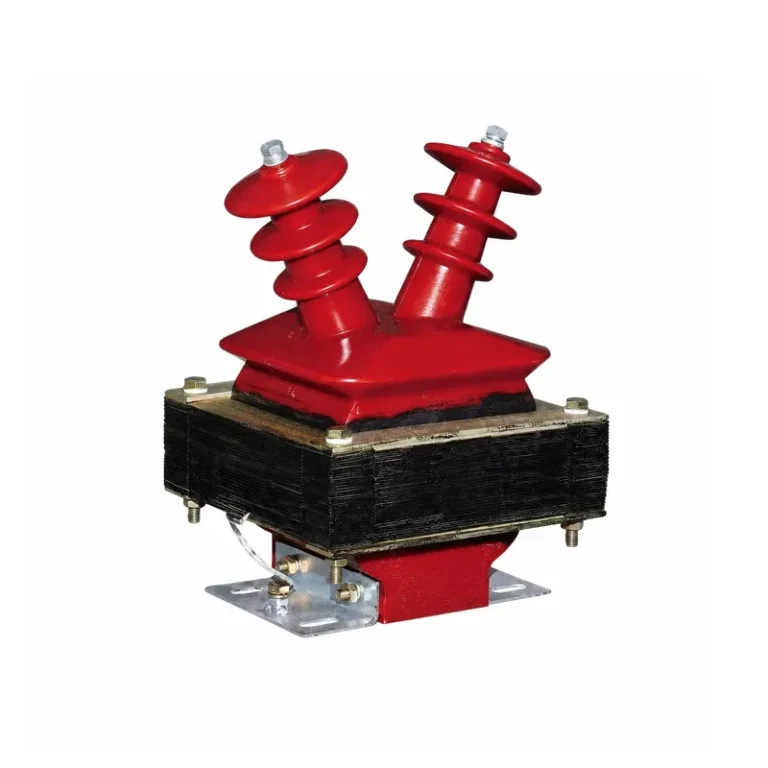
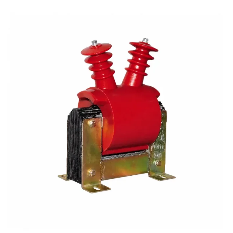
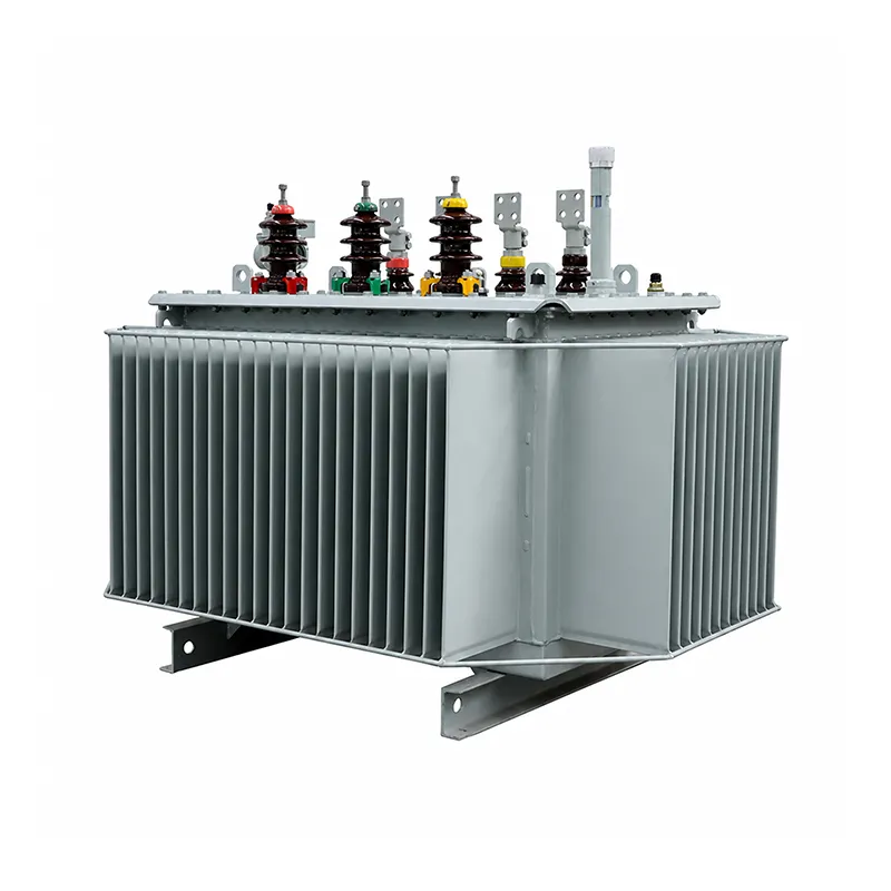
Product Overview
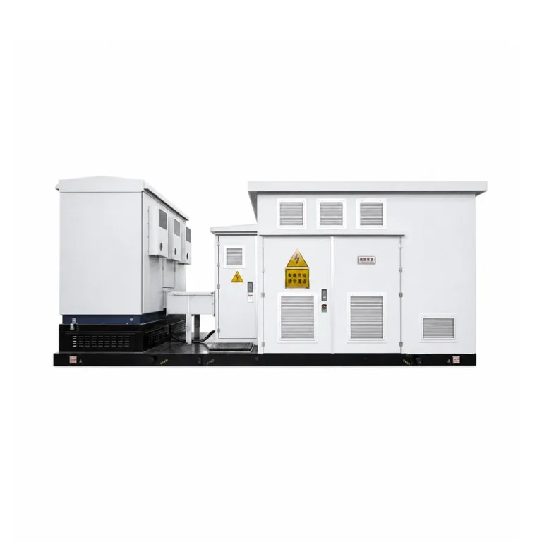
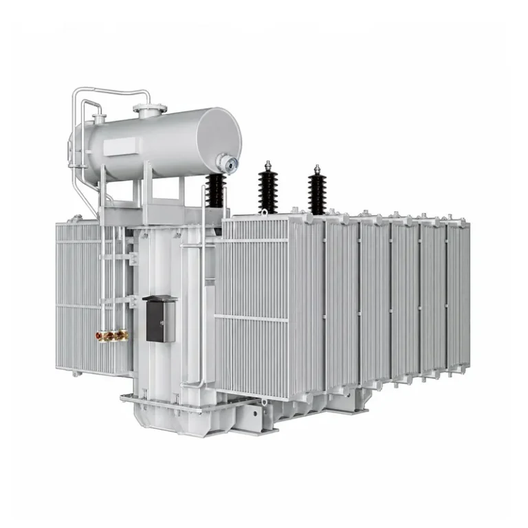
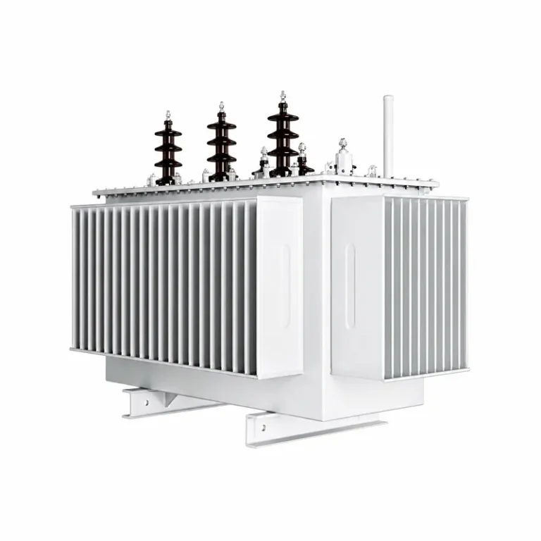
10kV & 20kV oil-immersed transformers are mainstream power distribution transformation equipment. With insulating oil for insulation and heat dissipation, they feature stable operation and easy maintenance. They can be installed standalone or integrated into box-type substations, widely applied in power grids, industrial parks, photovoltaic projects, municipal works and industrial & mining facilities to meet various medium-voItage power distribution demands.
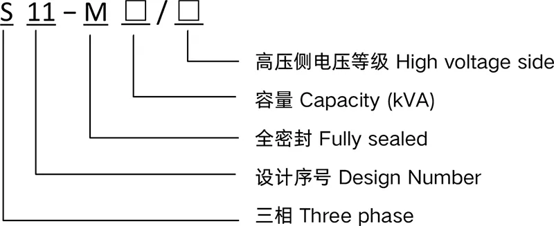
Model and Meaning
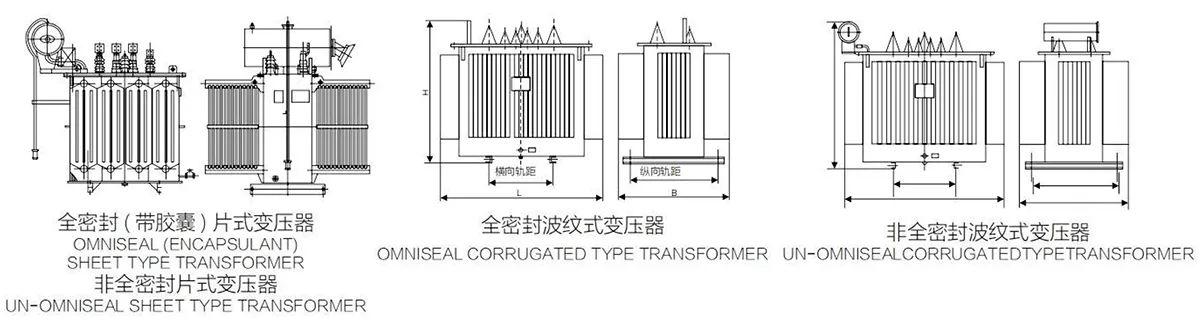
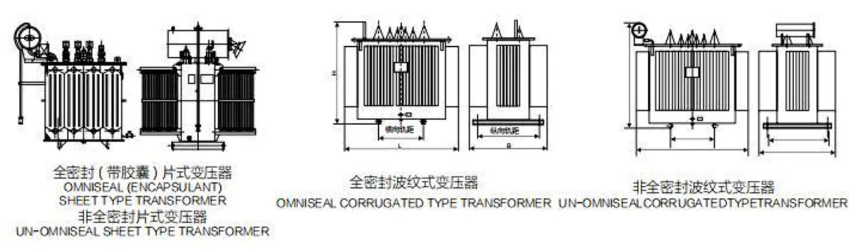
Transformer Product Standards
GB 1094.1-2013
GB 1094.2-2013
GB 1094.3-2017
GB 1094.5-2008
GB/T6451-2015
GB/T 7595-2017
GB/T 25289-2010
JB/T 3837-2016
Normal Service Conditions for Transformer
Altitude: not exceeding 1000m
Ambient temperature: Maximum air temperature: +40℃
Maximum daily average air temperature: +30℃
Maximum annual average air temperature: +20℃
Minimum outdoor air temperature: −25℃
Power voltage waveform approximates sine wave; three-phase power voltage is approximately symmetrical Installation environment: no obvious contamination
Seismic ground acceleration ag: horizontal value below 3m/s², vertical value below 1.5m/s² Indoor usage
Note: If special service conditions outside the above normal ranges are required, relevant conditions shall be stated when requesting quotation and placing orders
Technical Parameters
S11 Series 10ky distribution transformer
30kva 2500kva 3-phase duplex winding non-excitedtap-changing distribution transformer
| Rated capacity(kVA) | Voltage Combination and Tap range | Vector Group Symbol | Loss(kW) | No-load current (%) | Impedance Voltage (%) | Weight (kg) | Boundary Dimension (mm) (L×W×H) | Gauge vertical / horizontal (mm) | ||||||
| HV(kV) | % HV Tap Range | LV(kV) | No-load | Load | Body | Oil | Total | Omniseal | Un-omniseal | |||||
| 30 | 6 6.3 10 10.5 11 | ±5 ±2×2.5 | 0.4 | Dyn11 Yzn11 Yyn0 | 0.1 | 0.63/0.60 | 2.3 | 4.0 | 150 | 750 | 340 | 730×780×930 | 950×720×1000 | 400/400 |
| 50 | 0.13 | 0.91/0.87 | 2 | 220 | 950 | 440 | 800×750×965 | 1020×700×1035 | 400/400 | |||||
| 63 | 0.15 | 1.09/1.04 | 1.9 | 260 | 110 | 490 | 820×780×970 | 1140×740×1040 | 400/400 | |||||
| 80 | 0.18 | 1.31/1.25 | 1.9 | 300 | 120 | 580 | 840×800×1000 | 1060×720×1070 | 400/400 | |||||
| 100 | 0.2 | 1.58/1.50 | 1.8 | 350 | 120 | 660 | 850×840×1010 | 1105×760×1110 | 450/400 | |||||
| 125 | 0.24 | 1.89/1.80 | 1.7 | 400 | 130 | 700 | 860×900×1080 | 1120×800×1150 | 550/550 | |||||
| 160 | 0.28 | 2.31/2.20 | 1.6 | 480 | 160 | 840 | 1220×840×1100 | 1440×760×1290 | 550/550 | |||||
| 200 | 0.34 | 2.73/2.60 | 1.5 | 560 | 170 | 920 | 1250×860×1150 | 1470×780×1350 | 550/550 | |||||
| 250 | 0.4 | 3.20/3.05 | 1.4 | 640 | 180 | 1040 | 1260×850×1220 | 1480×780×1420 | 550/550 | |||||
| 315 | 0.48 | 3.83/3.65 | 1.4 | 800 | 200 | 1220 | 1340×900×1200 | 1560×840×1400 | 550/550 | |||||
| 400 | 0.57 | 4.52/4.30 | 1.3 | 980 | 240 | 1460 | 1380×900×1260 | 1600×840×1520 | 550/550 | |||||
| 500 | 0.68 | 5.41/5.15 | 1.2 | 1130 | 280 | 1710 | 1520×1000×1330 | 1740×960×1590 | 660/660 | |||||
| 630 | Dyn11 Yyn0 | 0.81 | 6.2 | 1.1 | 4.5 | 1350 | 330 | 2050 | 1580×1040×1270 | 1900×1040×1600 | 660/660 | |||
| 800 | 0.98 | 7.5 | 1 | 1610 | 400 | 2460 | 1650×1160×1400 | 1970×1160×1730 | 820/820 | |||||
| 1000 | 1.15 | 10.3 | 1 | 1690 | 450 | 3680 | 1750×1240×1460 | 2070×1240×1970 | 820/820 | |||||
| 1250 | 1.36 | 12 | 0.9 | 1910 | 500 | 3050 | 1800×1240×1550 | 2100×1240×1870 | 820/820 | |||||
| 1600 | 1.64 | 14.5 | 0.8 | 2330 | 590 | 3800 | 1830×1800×1930 | 1830×1800×1930 | 820/820 | |||||
| 2000 | 1.96 | 17.8 | 0.6 | 2750 | 780 | 4660 | 1950×1900×2080 | 1950×1900×2080 | 820/820 | |||||
| 2500 | 2.31 | 20.7 | 0.5 | 3350 | 920 | 5440 | 2060×1930×2130 | 2160×1930×2130 | 1070/1070 | |||||
Note 1: The load loss above the oblique in the table applies to Dyn11 or Yzn11; the load loss below the oblique line applies to Yyn0.
S11、SZ11 Series 10kv power transformer
630kva~6300kva 3-phase Duplex Winding Non-excited Tap-changing Power Transformer
| Rated capacity (kVA) | Voltage Combination and Tap range | Vector Group Symbol | Loss(kW) | No-load current (%) | Impedance Voltage (%) | Weight (kg) | Gauge vertical / horizontal (mm) | |||||
| HV(kV) | % HV Tap Range | LV(kV) | No-load | Load | Body | Oil | Total | |||||
| 630 | 6 6.3 10 10.5 11 | ±5 ±2×2.5 | 3 3.15 6.3 | Yd11 | 0.84 | 6.93 | 1.1 | 5.5 | 1780 | 450 | 2710 | 750/660 |
| 800 | 1.02 | 8.46 | 1 | 2100 | 520 | 3310 | 850/660 | |||||
| 1000 | 1.2 | 9.92 | 1 | 2580 | 600 | 3860 | 850/820 | |||||
| 1250 | 1.42 | 11.8 | 0.9 | 2880 | 700 | 4370 | 850/820 | |||||
| 1600 | 1.71 | 14.11 | 0.8 | 3400 | 780 | 4760 | 900/820 | |||||
| 2000 | 2.04 | 16.93 | 0.8 | 3800 | 890 | 5570 | 900/820 | |||||
| 2500 | 2.4 | 19.67 | 0.8 | 4350 | 960 | 6670 | 1070/1070 | |||||
| 3150 | 2.84 | 23.09 | 0.7 | 4940 | 1180 | 8500 | 1070/1070 | |||||
| 4000 | 10 10.5 11 | 3.15 6.3 | 3.48 | 27.36 | 0.7 | 5900 | 1580 | 9850 | 1070/1070 | |||
| 5000 | 4.16 | 31.38 | 0.7 | 6850 | 1760 | 11580 | 1070/1070 | |||||
| 6300 | 4.96 | 35.06 | 0.6 | 7920 | 1910 | 13650 | 1070/1070 | |||||
Note 1: According to requirements, the transformer can supply HV tap change ±2×2.5%
200kva~2500kva 3-phase duplex winding on-load tap-changing distribution transformer
| Rated capacity (kVA) | Voltage Combination and Tap range | Vector Group Symbol | Loss(kW) | No-load current (%) | Impedance Voltage (%) | Weight (kg) | Gauge vertical / horizontal (mm) | |||||
| HV(kV) | HV Tap Range % | LV(kV) | No-load | Load | Body | Oil | Total | |||||
| 200 | 6 6.3 10 | ±4×2.5 | 0.4 | Dyn11 Yyn0 | 0.39 | 2.91 | 1.5 | 4 | 980 | 260 | 1530 | 650/550 |
| 250 | 0.45 | 3.42 | 1.4 | 1070 | 310 | 1740 | 650/550 | |||||
| 315 | 0.54 | 4.1 | 1.4 | 1320 | 350 | 1980 | 650/550 | |||||
| 400 | 0.65 | 4.96 | 1.3 | 1580 | 430 | 2270 | 750/550 | |||||
| 500 | 0.77 | 5.9 | 1.2 | 1750 | 450 | 2500 | 750/660 | |||||
| 630 | 0.97 | 7.27 | 1.1 | 1900 | 530 | 2920 | 750/660 | |||||
| 800 | 1.13 | 8.89 | 1 | 4.5 | 2150 | 600 | 3320 | 850/660 | ||||
| 1000 | 1.38 | 10.43 | 1 | 2480 | 680 | 3710 | 850/820 | |||||
| 1250 | 1.58 | 12.4 | 0.9 | 2620 | 770 | 4200 | 850/820 | |||||
| 1600 | 1.94 | 14.79 | 0.8 | 3100 | 880 | 4850 | 900/820 | |||||
| 2000 | 2.27 | 18.69 | 0.6 | 3980 | 1080 | 5880 | 900/820 | |||||
| 2500 | 2.52 | 21.74 | 0.6 | 3950 | 1300 | 6370 | 1070/1070 | |||||
Note 1: According to requirements, the transformer can supply HV winding voltage 10.5kV and 11 kv.
Note 2: According to requirements, the transformer can supply LV 0.69kV
S13 Series 10ky distribution transformer
30kva~2500kva 3-phase duplex winding non-excited tap-changing dlistribution transformer
| Rated capacity (kVA) | Voltage Combination and Tap range | Vector Group Symbol | Loss(kW) | No-load current (%) | Impedance Voltage (%) | Weight (kg) | Boundary Dimension (mm) | Gauge vertical / horizontal (mm) | ||||||
| HV(kV) | HV Tap Range % | LV(kV) | No-load | Load | Body | Oil | Total | Omniseal | Un-omniseal | |||||
| 30 | 6 6.3 10 10.5 11 | ±5 ±2×2.5 | 0.4 | Dyn11 Yzn11 Yyn0 | 0.08 | 0.63/0.60 | 2.3 | 4.0 | 130 | 700 | 300 | 710×710×930 | 930×580×1000 | 400/400 |
| 50 | 0.1 | 0.91/0.87 | 2 | 200 | 800 | 400 | 730×710×1010 | 950×600×1080 | 400/400 | |||||
| 63 | 0.11 | 1.09/1.04 | 1.9 | 240 | 900 | 450 | 750×730×1040 | 970×630×1100 | 400/400 | |||||
| 80 | 0.13 | 1.31/1.25 | 1.9 | 280 | 100 | 520 | 760×740×1060 | 980×640×1120 | 400/400 | |||||
| 100 | 0.15 | 1.58/1.50 | 1.8 | 310 | 100 | 550 | 770×750×1130 | 1000×650×1200 | 450/400 | |||||
| 125 | 0.17 | 1.89/1.80 | 1.7 | 370 | 120 | 640 | 800×770×1150 | 1030×670×1220 | 550/550 | |||||
| 160 | 0.2 | 2.31/2.20 | 1.6 | 440 | 130 | 740 | 820×780×1240 | 1050×680×1310 | 550/550 | |||||
| 200 | 0.24 | 2.73/2.60 | 1.5 | 500 | 140 | 810 | 840×810×1260 | 1070×700×1330 | 550/550 | |||||
| 250 | 0.29 | 3.20/3.05 | 1.4 | 610 | 160 | 970 | 870×850×1300 | 1100×750×1370 | 550/550 | |||||
| 315 | 0.34 | 3.83/3.65 | 1.4 | 750 | 200 | 1200 | 1180×820×1390 | 1400×720×1460 | 550/550 | |||||
| 400 | 0.41 | 4.52/4.30 | 1.3 | 900 | 240 | 1420 | 1260×840×1450 | 1480×760×1520 | 550/550 | |||||
| 500 | 0.48 | 5.41/5.15 | 1.2 | 1050 | 250 | 1620 | 1300×860×1500 | 1560×800×1600 | 660/660 | |||||
| 630 | Dyn11 Yyn0 | 0.57 | 6.2 | 1.1 | 1240 | 280 | 1860 | 1370×890×1470 | 1630×930×1680 | 660/660 | ||||
| 800 | 0.7 | 7.5 | 1 | 4.5 | 1510 | 340 | 2250 | 1430×930×1580 | 1960×930×1680 | 820/820 | ||||
| 1000 | 0.83 | 10.3 | 1 | 1560 | 360 | 2410 | 1600×1100×1610 | 1860×1100×1720 | 820/820 | |||||
| 1250 | 0.97 | 12 | 0.9 | 1910 | 420 | 2930 | 1690×1140×1750 | 1950×1140×1860 | 820/820 | |||||
| 1600 | 1.17 | 14.5 | 0.8 | 2320 | 520 | 3630 | 1820×1650×2060 | 1820×1650×2060 | 820/820 | |||||
| 2000 | 1.26 | 17.8 | 0.6 | 2820 | 660 | 4550 | 1920×1750×2160 | 1920×1750×2160 | 820/820 | |||||
| 2500 | 1.49 | 20.7 | 0.5 | 3550 | 760 | 5470 | 2020×1910×2260 | 2020×1910×2260 | 1070/1070 | |||||
Note 1: The load loss above the oblique in the table applies to Dyn11or Yzn 11; he bad loss below the oblique line applies to Yyn0.
S11 Series 20ky distribution transformer
| Rated capacity (kVA) | Voltage Combination and Tap range | Vector Group Symbol | No-load Loss(kW) | Load Loss(kW) | No-load current (%) | Short-circuit Impedance Voltage (%) | ||
| HV(kV) | HV Tap Range % | LV(kV) | ||||||
| 30 | 20 | ±5 | 0.4 | Dyn11 Yzn11 Yyn0 | 0.1 | 0.69/0.66 | 2.1 | 5.5 |
| 50 | 0.13 | 1.01/0.96 | 2 | |||||
| 63 | 0.15 | 1.20/1.15 | 1.9 | |||||
| 80 | 0.18 | 1.44/1.37 | 1.8 | |||||
| 100 | 0.2 | 1.73/1.65 | 1.6 | |||||
| 125 | 0.24 | 2.08/1.98 | 1.5 | |||||
| 160 | 0.29 | 2.54/2.42 | 1.4 | |||||
| 200 | 0.34 | 3.00/2.86 | 1.3 | |||||
| 250 | 0.4 | 3.52/3.35 | 1.2 | |||||
| 315 | 0.48 | 4.21/4.01 | 1.1 | |||||
| 400 | 0.57 | 4.97/4.73 | 1 | |||||
| 500 | 0.68 | 5.94/5.66 | 1 | |||||
| 630 | 0.81 | 6.82 | 0.9 | 6.0 | ||||
| 800 | 0.98 | 8.25 | 0.8 | |||||
| 1000 | 1.15 | 11.33 | 0.7 | |||||
| 1250 | 1.38 | 13.2 | 0.7 | |||||
| 1600 | 1.66 | 15.95 | 0.6 | |||||
| 2000 | 1.95 | 19.14 | 0.6 | |||||
| 2500 | 2.34 | 22.22 | 0.5 | |||||
Note:Rated capacity 5000kVA and below transformer, the load loss above the oblique line in the table applies to Dyn11 connection group, the load loss below the oblique line applies to Yyn0
S13 Series 20ky distribution transformer
30kva~2500kva 3-phase duplex winding non-excited tap-chnanging distribution transformer
| Rated capacity (kVA) | Voltage Combination and Tap range | Vector Group Symbol | No-load Loss(kW) | Load Loss(kW) | No-load current (%) | Short-circuit Impedance Voltage (%) | ||
| HV(kV) | HV Tap Range % | LV(kV) | ||||||
| 30 | 20 | ±5 | 0.4 | Dyn11 Yzn11 Yyn0 | 0.08 | 0.66/0.63 | 2.1 | 5.5 |
| 50 | 0.1 | 0.96/0.91 | 2 | |||||
| 63 | 0.11 | 1.14/1.09 | 1.9 | |||||
| 80 | 0.13 | 1.38/1.31 | 1.8 | |||||
| 100 | 0.15 | 1.66/1.58 | 1.6 | |||||
| 125 | 0.17 | 1.98/1.89 | 1.5 | |||||
| 160 | 0.2 | 2.43/2.31 | 1.4 | |||||
| 200 | 0.24 | 2.87/2.73 | 1.3 | |||||
| 250 | 0.29 | 3.36/3.20 | 1.2 | |||||
| 315 | 0.34 | 4.02/3.83 | 1.1 | |||||
| 400 | 0.41 | 4.77/4.51 | 1 | |||||
| 500 | 0.48 | 5.68/5.40 | 1 | |||||
| 630 | 0.57 | 6.51 | 0.9 | 6 | ||||
| 800 | 0.7 | 7.88 | 0.8 | |||||
| 1000 | 0.83 | 10.81 | 0.7 | |||||
| 1250 | 0.97 | 12.6 | 0.7 | |||||
| 1600 | 1.17 | 15.22 | 0.6 | |||||
| 2000 | 1.26 | 19.74 | 0.6 | |||||
| 2500 | 1.49 | 21.73 | 0.5 | |||||
Note:Rated capacity 500kVA and below transformer, the load loss above the oblique line in the table applies to Dyn11 connection group; the load loss below the oblique line applies to Yyn0.