
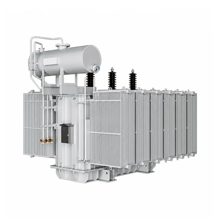
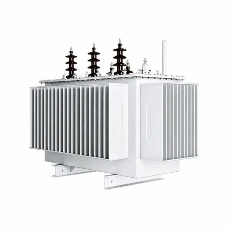
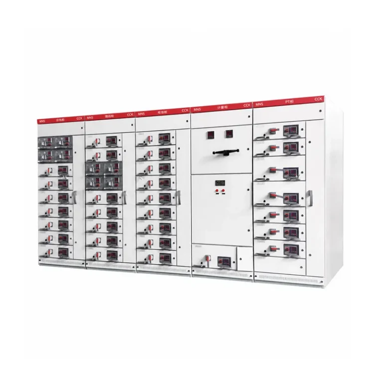
A current transformer vs voltage transformer choice is a series current scaler versus a shunt voltage scaler, so a 10–12 kV switchgear cubicle or overhead pole-switch job usually needs both. Secondary current and voltage follow a stated convention, a live CT secondary stays closed while a VT secondary stays unshorted, and indoor 10–12 kV work pairs a current transformer with a separate indoor voltage transformer.
The current transformer sits in series and holds a near-short-circuit secondary. The voltage transformer sits in shunt and holds a near-no-load secondary.
IEEE teaching uses a 120 V voltage-transformer secondary; JOHNN JDZ rows print 100 V.
Indoor 10 kV work pairs an LZZBJ current transformer with an indoor JDZ voltage transformer.
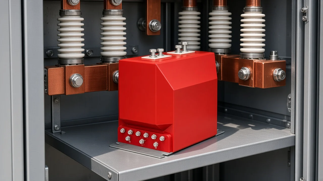
Both devices belong to the instrument transformer class. Isolation keeps the meter or relay circuit away from the high primary, which is the job a specifier is buying when both boxes appear on one cubicle drawing.
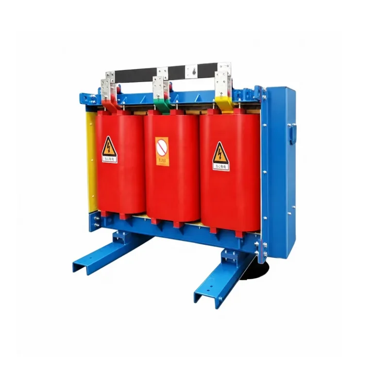
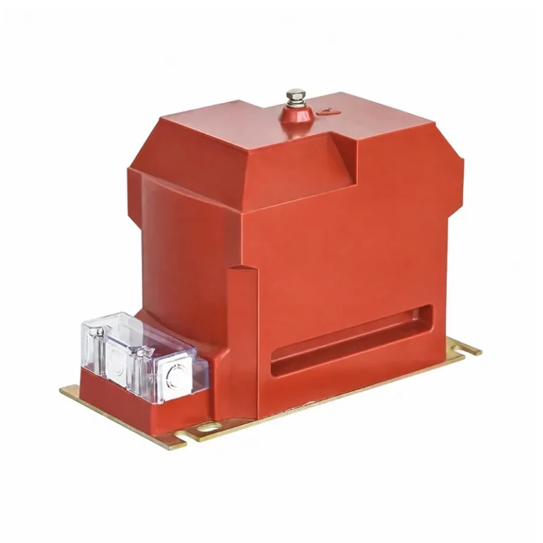
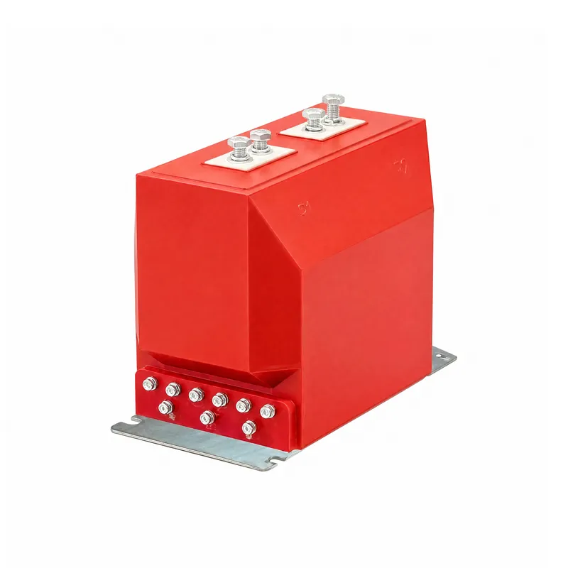
A red indoor epoxy current transformer in a metering cabinet is the current half of that pair. The voltage half is a separate shunt unit; that winding lives in its own indoor voltage transformer.
What Current Transformer vs Voltage Transformer Is Asking
A current transformer copies line current in series; a voltage transformer copies line voltage in shunt. Treating them as one machine with two labels puts the wrong secondary on the wrong connection.
The difference between current transformer and voltage transformer is the measured quantity plus the series-versus-shunt seat on the circuit. A current transformer copies line current; a voltage transformer copies line voltage.
Community threads still ask whether a CT and a VT are the same machine aimed at output current versus output voltage. They share a magnetic core and turns, but they are built as instrument transformers that measure while providing isolation, not as power transformers that move energy.
On a 10 kV switchgear drawing the two boxes sit next to meters and relays for that reason. One path carries a current copy; the other path carries a voltage copy.
Series Current Versus Shunt Voltage: How Each One Connects
A CT sits in series and works near short-circuit; a VT sits in shunt and works near no-load. That is the contrast a specifier can read on a single-line without opening a class table.
IEEE teaching names current transformers as the series type and voltage transformers, also called potential transformers, as the shunt type. The current transformer is often called a series transformer because the primary is the line conductor itself.
The difference between voltage transformer and current transformer on that drawing is shunt versus series. Put the CT in the current path; hang the VT across the voltage being measured.
| Point | Current transformer | Voltage transformer |
|---|---|---|
| Connection | Series with the line | Shunt across the line |
| Operating point | Near short-circuit secondary | Near no-load secondary |
| IEEE teaching secondary | 1 A or 5 A | 120 V |
| JOHNN printed VT secondary | — | 100 V on JDZ ratio rows |
| Live-secondary rule | Keep closed; never open | Keep unshorted; never short |
A window or bar current transformer often uses one primary pass through the core. That pass is still N turns, just with N = 1, which is why the red indoor block can look like a solid resin cube while the primary is only the conductor or the two top studs.
A CT-shaped sense transformer cannot stand in as a voltage transformer. Forum replies put it bluntly: that part is a current transformer, and it will blow up if you use it as a voltage transformer.
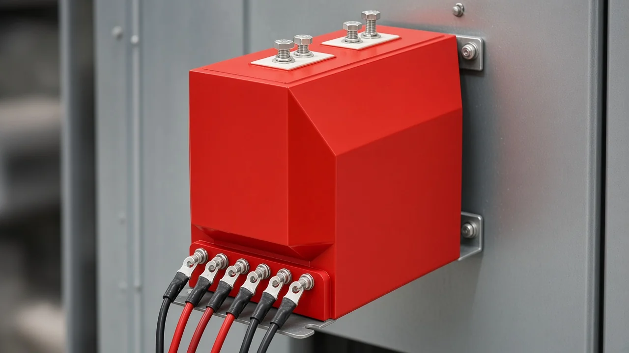
Secondary wiring on the panel is where the two operating points show up. Current leads stay a closed loop into the ammeter or relay; voltage leads stay a light burden into the voltmeter or protection input.
Secondary Convention, Ratio, and Isolation
The secondary is a standardized copy that keeps meters and relays isolated from the primary.
IEEE teaching uses a 1 A or 5 A current-transformer secondary and a 120 V voltage-transformer secondary. JOHNN JDZ-3, 6, 10Q rows print 3000/100, 6000/100, and 10000/100, so the printed secondary is 100 V.
Isolation separates the meter or relay circuit from the high primary system. In plain language, the panel side stays away from the line even while the copy of current or voltage remains usable.
Ratio is a turns relationship chosen from the primary quantity and that secondary convention. System voltage alone does not pick a current-transformer ratio, which is why an 11 kV lookup does not print one universal CT ratio.
A voltage-transformer ratio such as 10000/100 means the indoor JDZ row is scaling that primary voltage to the printed 100 V secondary. The current-transformer ratio is chosen the same way: primary current over the 1 A or 5 A convention.
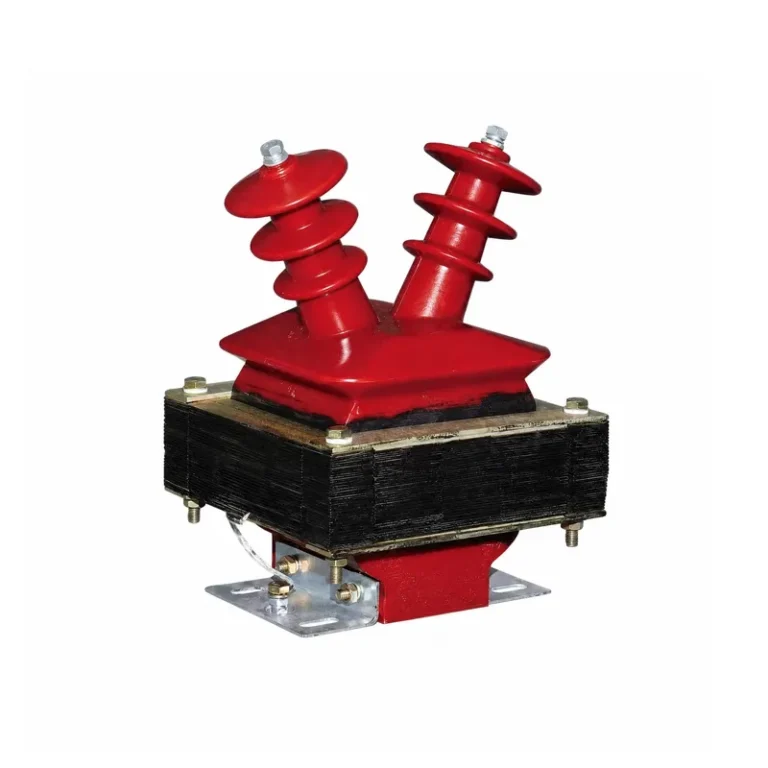
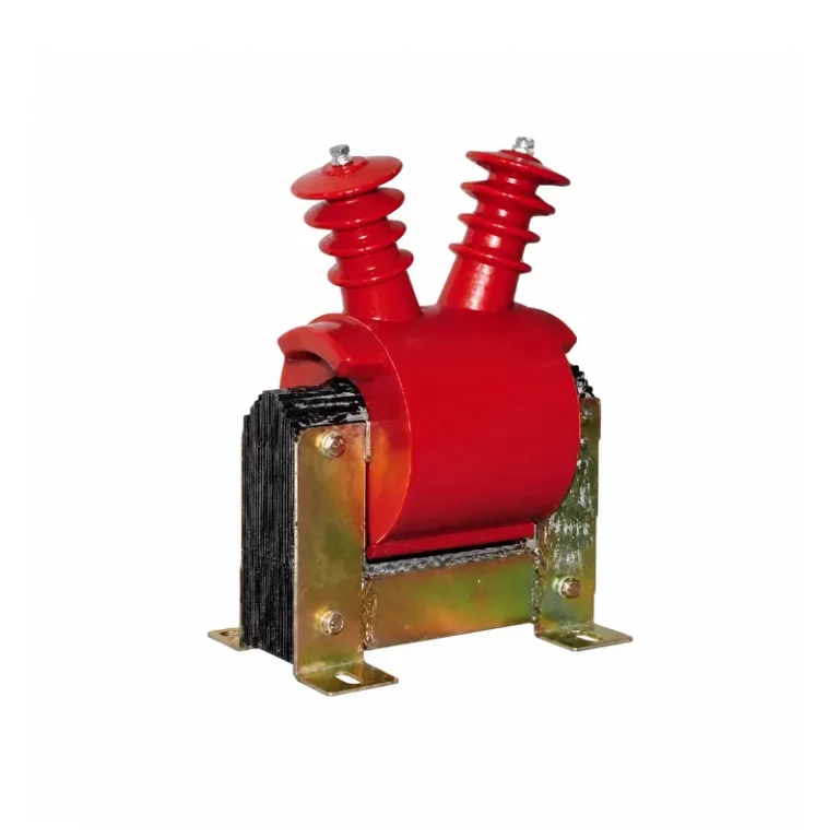
The JDZ indoor rows cover 3 kV, 6 kV, and 10 kV.
Burden and Accuracy Class: Metering Versus Protection
The connected instruments and cables set the burden: their total impedance. Exceeding the rated burden moves the copy off the accuracy class the specifier paid for.
Specifiers read a metering or protection label at a stated test. IEC 61869-1 lists metering accuracy classes 0.1, 0.2s, 0.2, 0.5, 0.5s, 1 and 3.
IEEE metering current-transformer classes are 0.3, 0.6, and 1.2. Relaying examples on that IEEE summary include C100 or C400, the number being the secondary voltage the CT can develop at 20 times rated secondary current without exceeding ten percent ratio error.
LZZBJ9-10C1 prints class-combination headers 0.2S/10P10, 0.5S/10P10, 0.2/10P10, and 0.5/10P10. Those headers show a metering core and a protection core on one indoor 10 kV body.
Metering cores are judged near rated value. Protection cores are judged at multiples of rated current, which is the IEEE C-class and IEC 5P–10P language.
Core-versus-core current-transformer detail is already on current transformer metering and protection: a complete buyers guide.
Why a Live CT Secondary Stays Closed and a VT Secondary Stays Unshorted
Do not leave a live CT secondary open; do not operate a VT into a short circuit. The two rules are swapped because the two operating points are swapped.
A current transformer should never be left open-circuited, just as a voltage transformer should never operate into a short circuit. If an ammeter has to come off a live CT, short the secondary first.
Opening a live CT secondary raises a dangerous voltage and can arc. A shorted VT secondary asks a near-no-load device to feed a fault on its own instrument winding.
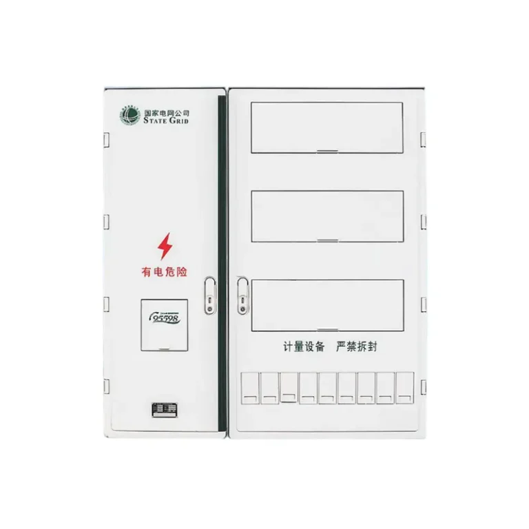
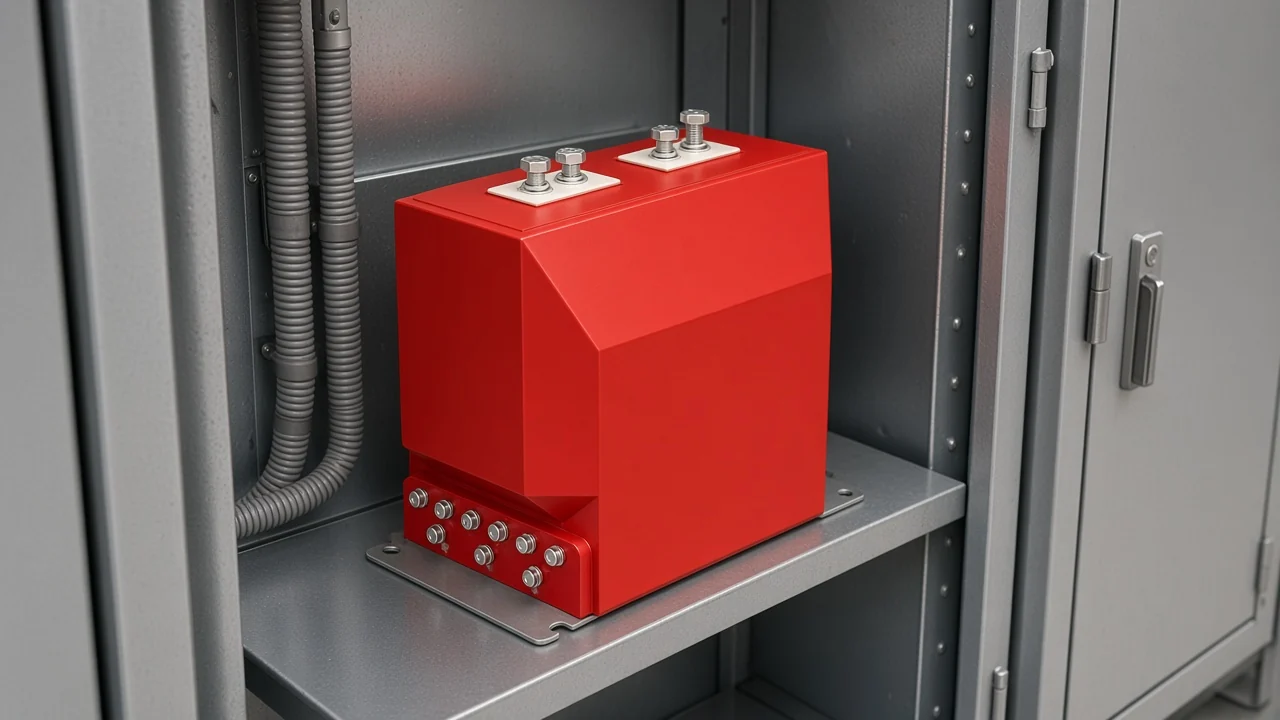
That pair is the field habit on a metering cabinet door. Keep the current loop closed and the voltage loop unshorted while the primary stays energized.
Voltage Transformer, Potential Transformer, and Power Transformer
VT and PT are the same shunt instrument transformer; neither is a power transformer. A voltage transformer vs current transformer search still lands on that pair: the shunt voltage scaler and the series current scaler.
Voltage transformers, also called potential transformers, are a parallel-connected type of instrument transformer. Potential transformer is another community name for the same shunt voltage scaler.
From the field: Current transformers and voltage transformers are separate animals from power transformers. They are used to measure a current or voltage while providing isolation — practicing-engineer wording on isolation versus energy transfer.
A distribution transformer or other power transformer is built to move energy at a useful efficiency. An instrument transformer is built to hold ratio and phase for meters and relays, which is why a bench 120 V control transformer is a poor stand-in for either job.
IEEE Standard C57.13 governs the instrument-transformer teaching used above. IEC 61869-2:2012 covers newly manufactured inductive current transformers from 15 Hz to 100 Hz and is read with IEC 61869-1.
IEC 61869-3:2011 is the inductive voltage-transformer counterpart for the same 15 Hz to 100 Hz band. Those IEC parts replace the older IEC 60044-1 and IEC 60044-2 catalog names.
Choose the Indoor Current Transformer That Pairs With a Voltage Transformer
A medium-voltage cubicle or pole-switch bay needs the current copy and the voltage copy as two devices. Outdoor current transformers still take a separate indoor voltage transformer.
Indoor 10 kV work pairs an LZZBJ9-10C1-class CT with an indoor JDZ voltage transformer. Outdoor LZW current transformers still need a separate indoor voltage transformer, because JOHNN’s voltage shelf lists indoor families only.
The current transformer hub groups outdoor LZW and LZZW units for pole-mounted 10–12 kV work and indoor LZZBJ units for switchgear, metering cabinets, and distribution panels. LZW32-12 is the outdoor 12 kV pole-switch current transformer on that shelf.
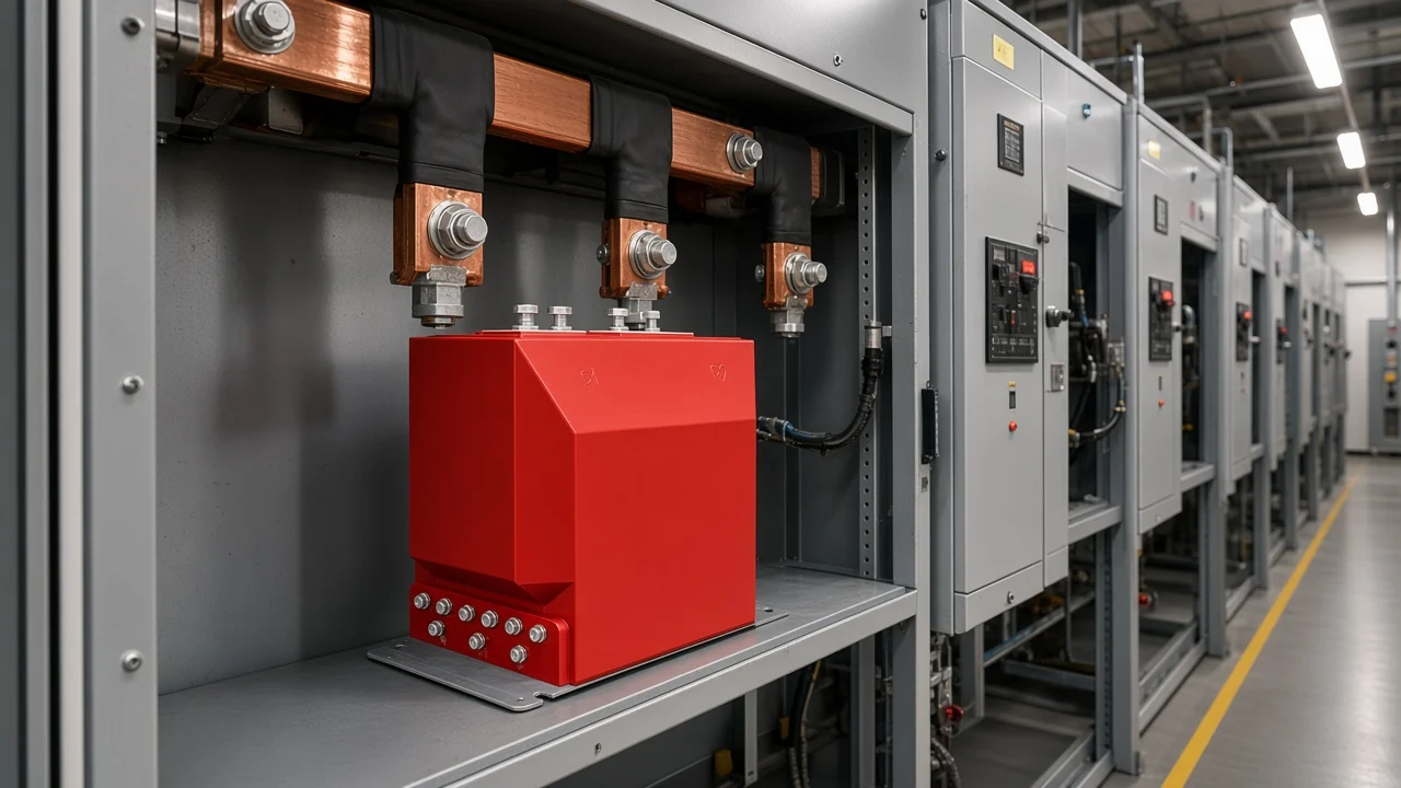
The voltage transformer hub lists indoor JDZ, JDZC, JDZ10, and JDZX families for 3 kV, 6 kV, and 10 kV voltage measurement and protection signal conversion. JDZ-3, 6, 10Q is the indoor voltage-transformer counterpart with printed 3000/100, 6000/100, and 10000/100 rows.
LZZBJ9-10C1 is an indoor current transformer designed for 10kV medium-voltage power systems. Open the LZZBJ9-10C1 indoor 10 kV current transformer when the cubicle needs the current half of that pair.
| Item | What the pair uses |
|---|---|
| IEEE C57.13 teaching | Series CT at 1 A or 5 A; shunt VT at 120 V |
| IEC 61869-2 | Inductive current transformers, 15 Hz to 100 Hz |
| IEC 61869-3 | Inductive voltage transformers, 15 Hz to 100 Hz |
| Indoor current half | LZZBJ9-10C1 for 10 kV switchgear and metering cabinets |
| Outdoor current half | LZW32-12 and the LZW / LZZW 10–12 kV pole-switch family |
| Indoor voltage half | JDZ-3, 6, 10Q at 3000/100, 6000/100, and 10000/100 |
A pole-mounted feeder that already has an outdoor current transformer still needs the indoor voltage transformer if the panel must measure voltage. A voltage-only job can stay on the JDZ page; do not treat the current-transformer SKU as a second quote form.
The instrument transformer hub keeps both families on one shelf so the pair can be browsed together. Current measurement and protection signal conversion stay on the CT; voltage measurement and protection signal conversion stay on the VT.
FAQ
What’s the difference between a current transformer and a voltage transformer?
A current transformer sits in series and copies current; a voltage transformer sits in shunt and copies voltage. One works near a short-circuit secondary, the other near no-load.
Is a voltage transformer the same as a potential transformer?
Yes. Potential transformer is another common name for the same parallel-connected voltage transformer.
Why can’t I use a current transformer as a voltage transformer?
A current transformer is built for a near-short secondary and a series primary. Treating a CT-shaped part as a voltage transformer asks it to do a shunt, near-no-load job it was not wound for.
What should I do before I remove an ammeter from a live CT?
Short the CT secondary first. Never use a CT-shaped part as a voltage transformer.
Does system voltage by itself set the CT ratio?
No. An 11 kV system voltage does not print one universal CT ratio; ratio is chosen from primary current and the 1 A or 5 A secondary convention.
Are current transformers AC or DC devices?
AC instrument current transformers and voltage transformers are the topic. IEC 61869-2 and IEC 61869-3 cover inductive units from 15 Hz to 100 Hz.
When does a medium-voltage project need both a CT and a VT?
Whenever the panel must see current and voltage, or must compute power, energy, or impedance from both. A 10–12 kV cubicle or pole-switch bay usually needs the series current copy and the shunt voltage copy.
Does JOHNN already have a metering-versus-protection CT article?
Yes. The live buyers guide already owns metering cores versus protection cores inside current transformers, and that page remains the place for 0.2S versus 10P depth.