
Whether you’re specifying equipment for a new substation, upgrading switchgear in an industrial facility, or sourcing CTs for a metering project, understanding how current transformer metering works — and where it differs from protection applications — is essential for getting accurate billing data and reliable fault detection.
What Is a Metering Current Transformer?
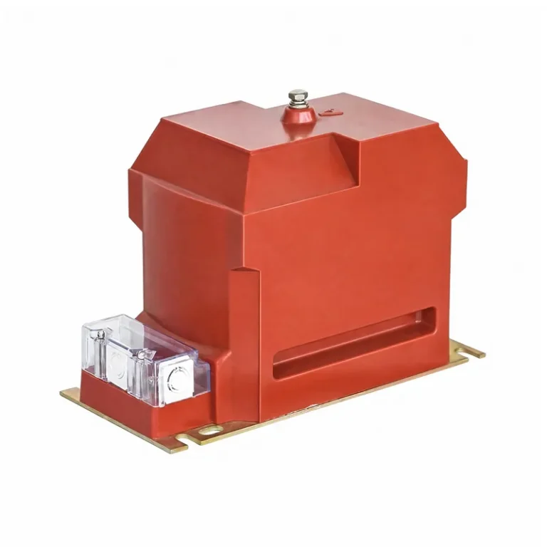
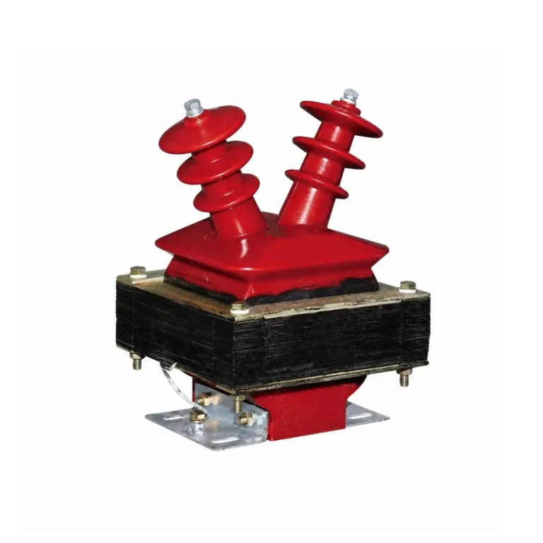
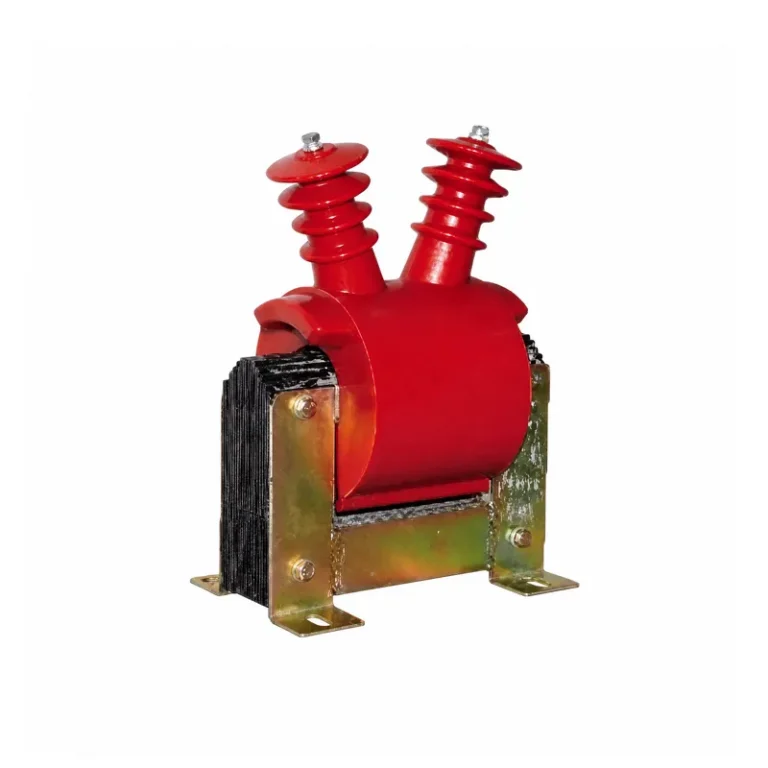
A metering current transformer is an instrument transformer that steps down high primary currents to a standardized low-level output — typically 5 A or 1 A — so that energy meters, power monitors, and panel instruments can measure current safely and accurately. It provides galvanic isolation between the high-voltage primary conductor and the low-voltage measurement circuit, protecting both equipment and personnel.
The core function of a current transformer in metering applications is straightforward: the ratio of primary to secondary current is determined by the inverse ratio of winding turns, so a CT with 1 primary turn and 200 secondary turns reduces the primary current to 1/200th of its value. That scaled-down signal is what your meter or monitoring device actually reads.
Metering vs. Protection CTs: What’s the Difference?
It’s a common point of confusion. Both types are current transformers, but they’re optimized for entirely different jobs.
Metering CTs need high accuracy near the rated current. ANSI defines metering accuracy classes of 0.3, 0.6, and 1.2, with maximum ratio errors of ±0.3%, ±0.6%, and ±1.2% at rated current, respectively. IEC standards specify classes 0.1 through 5. These CTs are designed to saturate early — the lowest possible safety factor — so that high fault currents don’t damage sensitive metering equipment.
Protection CTs, by contrast, must maintain accuracy during fault conditions, often at currents 10 to 20 times the rated value. They’re characterized by their accuracy limit factor (ALF) and accuracy classes like 5P or 10P. Instead of saturating early, a protection CT must have a high saturation threshold to reproduce fault current waveforms faithfully for relay operation.
Modern dual-purpose CTs with separate metering and protection windings can serve both functions in a single assembly, which is common in space-constrained switchgear.
Types of Current Transformers for Metering
Selection starts with the physical configuration. The most common types for metering include:
- Window-type (through-core) CTs — the primary conductor passes through an aperture. Widely used in panel boards and switchgear where conductor routing is straightforward[reference:9].
- Bar-type CTs — the primary conductor is integrated into the assembly during manufacturing, providing a fixed, factory-tested configuration.
- Split-core CTs — hinged or bolted halves that open to encircle existing conductors. Ideal for retrofit projects because they can be installed without de-energizing the circuit.
- Wound-primary CTs — the primary winding is an integral part of the CT, used in lower-current applications where precise ratio matching is needed.
Beyond construction, CTs are also classified by core material. Silicon steel cores offer good permeability at power frequency and are standard for metering. Nanocrystalline cores are chosen for applications requiring wider bandwidth or better performance under harmonic-rich conditions.
How to Select a Current Transformer for Metering: 5 Key Steps
Getting the selection right matters — a mismatched CT causes billing errors, regulatory non-compliance, and in some cases equipment damage. Here’s a practical approach:
1. Determine the CT Ratio
Don’t simply match the CT ratio to the load’s rated current. The goal is to have normal operating current fall within 30% to 60% of the CT’s rated primary current. This keeps the CT in its most accurate operating range while leaving headroom for startup surges and overloads. For a motor with a 100 A rated current, a 150/5 or 200/5 CT is often a better choice than 100/5.
2. Choose the Accuracy Class
For revenue billing and tariff metering, 0.2S or 0.5S class CTs are standard. For industrial division metering, class 0.5 or 1 is acceptable. For panel instruments and general monitoring, class 0.5 or 1.0 is sufficient. Using a measurement-grade CT for billing will almost certainly fail regulatory requirements.
3. Calculate the Burden
Burden is the total impedance the CT must drive — the connected meter, relay, wiring resistance, and any other devices in the secondary circuit. Sum these values and ensure they don’t exceed the CT’s rated VA. As a rule of thumb, the operating burden should be between 25% and 100% of the rated burden to maintain specified accuracy. Overburdening a CT causes current errors and inaccurate readings.
4. Select Secondary Current: 5 A or 1 A
For short secondary runs inside a switchgear cabinet, 5 A is the conventional choice. For long cable runs — say, from an outdoor CT to a control room meter — 1 A secondary reduces voltage drop and maintains accuracy over distance.
5. Verify Polarity and Installation Orientation
CT polarity matters. The primary terminals are marked P1 (source side) and P2 (load side); the secondary terminals are S1 and S2. If reversed, power readings become negative and directional protection may fail. Always confirm that P1 faces the supply side and that S1/S2 wiring matches the meter’s terminal markings.
FAQ: Common Questions About Current Transformer Metering
What is a metering current transformer?
A metering CT is an instrument transformer that converts high primary current into a proportional low-level secondary current (usually 5 A or 1 A) for energy meters and monitoring instruments. It provides electrical isolation and enables accurate, safe current measurement on high-voltage or high-current circuits.
How do current transformers measure current?
A CT operates on electromagnetic induction. Alternating current in the primary conductor establishes a magnetic flux in the core, which induces a proportional current in the secondary winding. The ratio between primary and secondary current equals the inverse ratio of the winding turns.
How to select a current transformer for metering?
Start with the ratio (size it so normal load is 30–60% of rated primary current), then choose the accuracy class based on application (0.2S or 0.5S for billing), calculate the total secondary burden in VA to confirm it’s within the CT’s rating, and pick 5 A or 1 A secondary based on cable run distance. Finally, verify the installation orientation and polarity.
Practical Tips for Installation and Maintenance
Even a perfectly specified CT will underperform if installed incorrectly. A few critical points:
- Centre the primary conductor in the CT window. Off-centre or angled conductors distort the magnetic field and introduce measurement errors.
- Never open-circuit the secondary while primary current is flowing. Without a burden, the core saturates and dangerously high voltages appear at the secondary terminals.
- Ground the secondary circuit at one point only — typically at the meter end — to avoid circulating currents.
- Use shielded twisted-pair cable for the secondary wiring, with the shield grounded at one end, to minimise electromagnetic interference.
Following these practices keeps the metering chain accurate and the system safe throughout its service life.
Current transformer metering is a critical link in any electrical measurement system. From understanding the fundamental difference between metering and protection CTs, to selecting the right ratio, accuracy class, and burden, every decision affects the reliability of your billing data and the safety of your installation. Whether you’re specifying equipment for a new project or troubleshooting an existing installation, keeping these principles in mind will help you choose CTs that deliver accurate, consistent performance over the long term.